Tuesday, September 30, 2014

Switch Pod Buttons Installation


After much tossing and turning in my sleep last night with how to best install my switch pod buttons I came up with an idea that works. Although I would have preferred not to have had screws visible at he front I could not think of a better way given that the buttons board had no mounting holes of any kind, my guess is that they are probably configured for a different switch pod base than the one I'm using so I had to make it work best I could.


What I ended up doing was cutting out 4 pieces of Lexan plastic and contact cementing some thin high density foam rubber onto the back of each piece of plastic, then drill a hole in each side for the screw to pass through. This way the plastic would press against the back of the boards at the top and bottom, the high density foam rubber would act as a cushion to protect the back of the board from any pressure from the plastic as it was screwed down.


I also cut a couple of plastic bezels out of some of that scrap plastic I had from that salvaged old TV set that got dismantled for odds and ends. The screws go right through the face of the switch pod base and to the sides of the switch buttons board and through the holes drilled into the sides of the Lexan plastic strips with the high density foams rubber on the backs of them. I was looking for black screws but no such luck so I'll paint these when it's time. I figure if I'm sort of forced to have screws they might as well blend as much as possible. Overall I'm pretty happy with the way they look. Once painted they should look pretty sharp.


Monday, September 29, 2014

Switch Pod Switches Prep Work


I measured my holes big enough to allow the buttons to poke through the face of the switch pod on both sides. I had to do a little cutting of that aluminum bracing support metal I had glassed in there. It would have been nice to have had measurements for the switches before I had glassed in that metal bracing, but Oh well, that's my impatience to get things done for you. ;) Anyways it was not a super difficult job to Dremel out the aluminum where needed.

The switch pod button fire nicely through the holes and now I need to come up with a good method of securing the buttons in place, preferably in a way that should I ever need to remove them for maintenance I will be able to do it with a minimum amount of fuss.

Here is a shot of one of the switch pod buttons just resting in place seen from the back side of the pod's open back panel. As you can see I did go with the Velcro option of holding a back plate on. Here the back plate is removed so I can get my buttons mounted into the pods. I'm not sure of a good way to do this just yet. Perhaps some kind of bracket shaped sort of like an upside down elongated "U" could be fabricated out of Lexan plastic and then screwed onto aluminum mounting tabs that could be glassed into the back of the pods. Maybe some high density foam rubber on the insides of the plastic "U" bracket would provide enough cushion and support needed to hold the buttons firmly in place? Hmmmm... I'll have to see what I can come up with along those lines, try out a few ideas and see what will look like it will have the best chance of working really well.


Here is a view of me just holding one of the switch pod buttons in place from the front side of the pod. Looks good so far but like I say I just need to work out a good method of securing them in from the back whilst still making them easy to remove at any future time.

The other thing is I need to make sure the right buttons go on the right side, that's if that is even very important or not? I'll have to check some reference pictures and see if there is any right or wrong way to the button order. Seeing how the buttons are removable and replaceable with other buttons I can't REALLY see that being too big on an issue though.

Switch Pod Buttons Arrive From KRW

Yayyy... the Switch Pod switches along with the extra buttons set arrived in the mail today from Knight Rider World. Now I can install these into my switch pods, then do another test fit of the dash so I can make sure my switch pods get mounted on in the right position, then I can glass them onto the dash.

I noticed that on the switches boards there are no mounting holes so I'm not sure how these get mounted into the pods. I'm sure I'll figure a way. Maybe cut a hole big enough for the switches to poke through the face of the pods and then use the edge of the boards as a stop or brace and then secure something over top of them inside of the back of the pods to secure them in place.... Hmmmm... going to require a little thought on that. I'm wondering how others have done this with their pod switches installation. Also need to figure out the wiring for these too. The red and black are obvious and I think the white is for the DTMF tones.

On an additional note I wonder how you can make each button do something different? That I would not mind figuring out just so I can solder on the necessary wires and run them through the pod to the back of the dash and label them for easy identification later.... that's if that is possible with this button set that is??

Saturday, September 27, 2014

Friday, September 26, 2014

VB Theme Cut Off Button Update


On the left my custom button name plate as it arrived from the engravers and on the left the button installed next to the Voice Projection button. When I solder the wires from the connector that attaches to the dash and to the Voice Box this button when in the "On" position will disable the Knight Rider Theme from playing during the dash's start up sequence.

 I have an extra custom name plate and button if anyone is interested, just eMail me at: mdk.graphics@rocketmail.com
$30.00 shipping included,
shipping may be more depending on location.


New Scanner Lenses


I cut to shape one of the scanner lenses I got from Charodon plastics. As you can see the new custom lens fits way better than the one that came with the scanner. It fits nice and close to the top of the hood and also follows the inverted "V" shape better too. If your front nose and scanner fit was anything like mine here is my plan for the plastic lens that fits much better.


Thursday, September 25, 2014

Cyberdyne Speed Sensor Worked into The Wiring Diagram

I added the Cyberdyne Speed sensor into the wiring scenario to further give the whole wiring scheme a more completed diagram. I'm still trying to get ABSOLUTE confirmation that what I have here is the correct wiring order for the dash electronics. Most of the wire used to connect the electronics is 18 AWG or higher. All of this gets power through the Ignition wire run through the Step Relay and the Power switch among the PANP group. The PANP switches in this scenario are controlled by the VB (Voice Box) and all of the electronics used are from Knight Rider World (Italy). Lately I have been trying to use my Multimeter to see if I have my wires all correct.

Saturday, September 20, 2014

General Update - Getting Close To Having The Dash Wired

It's taken a lot of annoying questions and pestering to finally get what I think is the correct wiring order of the dash electronics. I'm a little surprised that the suppliers of these electronics don't put something a little more inclusive as far as wiring instructions given that I can't possibly be the only one out there attempting a project like this that knows very little about  electronics. It would make the job go a hell of a lot smoother and take less time instead of all the running around in different forums posting question after question trying to get confirmation on if something is correct, if I understand it right... I am trying to learn, and it's by the asking of questions we learn is it not?

Anyways I was to learn that I needed a Step relay for the Power switch among the P.A.N.P. group of push button switches. It then too a very long time (All day) to find a place on-line willing to ship to Canada... that was a joy treat of frustration I'm here to tell you. So I finally get the one recommended to me only to discover it has six terminals verses the one in the diagram that has only four. To make things even more confusing the diagram originally did not have the terminals numbered, I had to pester, and pester until I got that information. So that was part of the problem finally licked as to just what the hell those terminals were on the Step Relay.

Next issue was how does this relay relate to the one I was recommended. So again it was back to the pestering to try and get an answer to that nagging question. I was then told NOT to use terminals 3 and 4 on the Step Relay, which was fine considering my Relay seemed to be missing those screws for some reason, perhaps that very reason? I just don't know.


So now we know what NOT to use on the Relay but still no definitive or certain information on the wiring order to the Relay. We all know these are important things to know because these are very expensive electronics and we don't need to be replacing them due to faulty wiring now do we??

Some more pestering later (all of this pestering takes days btw), I got information that 3 and 4 on that Relay don't do anything, which may explain the missing screws, and that A1 on the Relay is 3 on my schematic, and that 1 and 2 are the switch. I hope to Hades that is correct?

We are getting closer, and closer to where I should be able to fire up the dash electronics for a test.... and I hope NOT the word "Fire Up." I will do a lot more pestering yet before I feel confident enough to hook the dash up to power and give everything a test before fitting the dash into the car.

Another thing that had been bugging me was trying to figure out how people test out their dash electronics out side of their cars once they have put everything together. I was told that something like a Battery Booster Pack like the one I have here is good for testing out the electronics. So I picked up a Motomaster Eliminator Booster pack. My next dilemma albeit a small one was the type of connector the Booster Pack has. All I need is a Positive and a Ground wire to hook ultimately up to the dash electronics. But not being very familiar with those "Cigar" type plugs I was not sure which of the connections points was which. So into Photoshop to do what I'm best at and that's creating graphics to make an illustration of the type of connector to better get my question across. Now my suspicion was that the middle connection point was the (+) Positive because it had the fuse inside of it. The side spring clips had to be the (-) Ground I figured.... But again best to be doubly sure about this stuff.


As it turns out this is the way these plugs are generally configured. I was told that sometimes only one of the side spring clips is actually grounded, wouldn't that just figure?? So I took apart both ends of the plug to have a look. Fortunately both sides of the plug side springs are grounded. No I could I would imagine just place small Alligator Clips onto one of the Side Springs (-) and one onto the Tip of the plug (+) but that seems a bit of a giggly connection should the wire accidentally fall or get bumped and then the clips could just simply pop off, most likely the tip seeing how it's smooth and not much for the Alligator clip to hold onto. I went out and bought another type of "Cigar" plug that has a thinner wire on. 


So now I'm wondering if that thin wire would be strong enough to handle the current for all of the dash electronics. I was told that the Ignition wire is sufficient for powering your dash electronic too.

A lot of these issues mentioned above are things I am trying g to get confirmation on, good solid answers, Yay or Nay, otherwise I'm very apprehensive about hooking my dash wires up to power, it has to be done at some point but I'm trying to get as much information and confirmation of that information as possible before I do so. One other thing I am not sure of is that if you look at my first diagram at the top of this posting you can see how I have the dash electronics wired to each other in a "Daisy Chain" sort of fashion, I have been told this is OK, I just used the wires that were attached onto the dash electronics when they arrived from Italy. I'm wondering if I should change them to a slightly thicker 18 AWG wire or if they are more than fine with the wires they came with...??

Anyways.... So many variable to try and sort through.... it's a no wonder I have not gotten this dash installed over the summer months. Research, research, research takes a lot of time.

Tuesday, September 16, 2014

My VB Theme Cut Off Button Plan


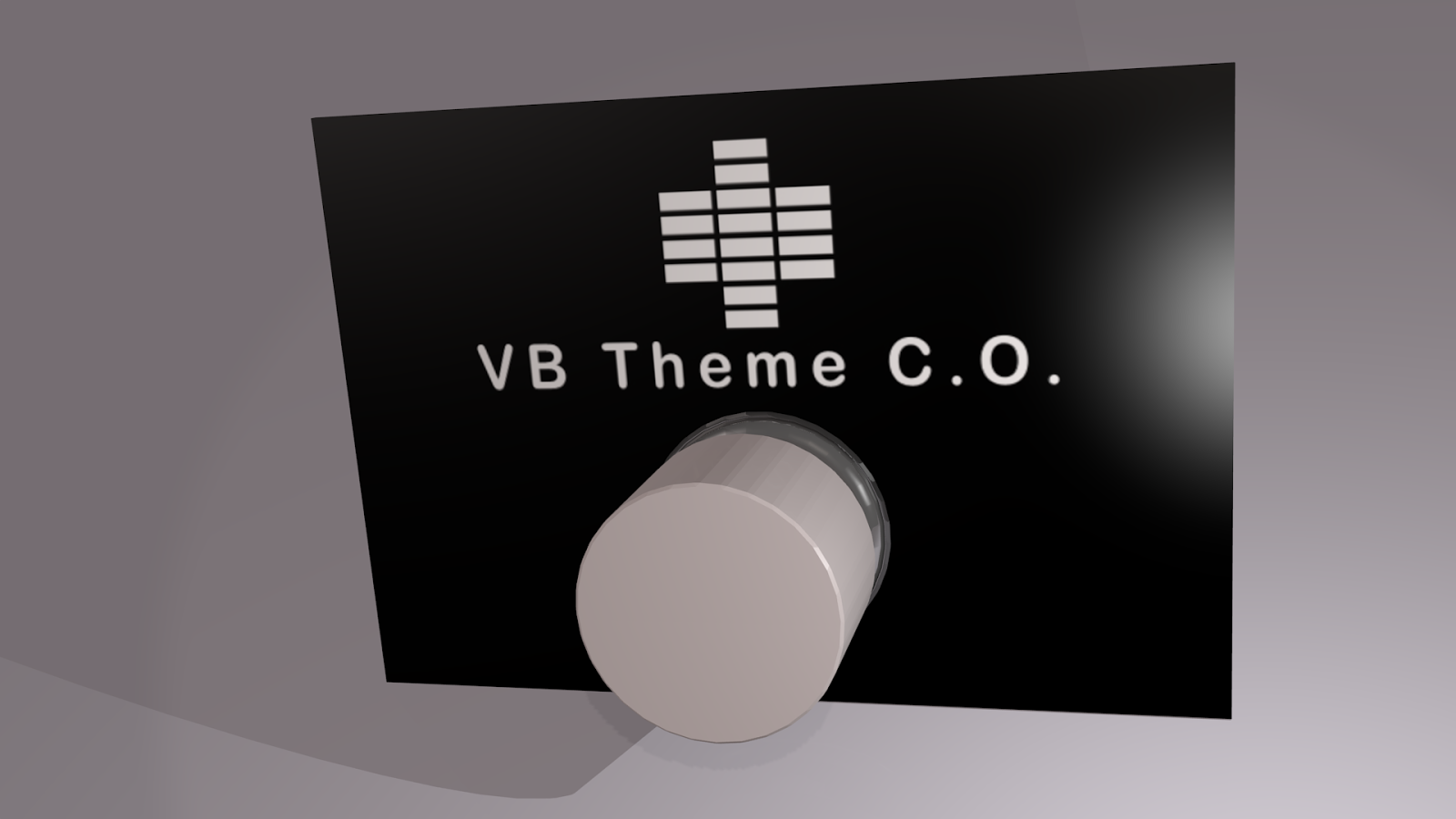
Here is a 3D mock up of what my finished Voicebox startup theme cut off button should look like. Rendered in Blender 3D.

K.I.T.T.s V.B. Startup Theme Cut Off Button

I made a few very minor changes to the wiring diagram for the Voicebox to include the Knight Rider Theme Cut Off switch and also the DTMF tones request switch. I have been told that 20 or so switches can be wired to the DTMF Tone Request Terminal using this wiring method.

I made a design for an engraved switch bezel for my Voicebox Start up Theme Cut Off or V.B. Theme C.O. for short to go on the engraved bezel, black with white engraved text. I'm getting a local engraver to do it up for me as they are practically just up the street at 1843 Portage Ave.

This is my artwork for my custom engraved V.B. Theme C.O. button bezel. I made a little icon to represent the Voicebox. Feel free to use my design in your own K.I.T.T. replicas if you are wanting a similar button and you want a nice push button name plate. A hole will be included just under the text big enough to accommodate my button.


This is the type of Push ON Push OFF button I am going to use to perform the simple task of jumping the connection on the Voicebox Ground and COM terminals, by pushing the button to the ON position when the startup sequence goes through it's startup routine the included Knight Rider theme will be deactivated. If the button is in the OFF position then the theme will play during the startup sequence. Very simple but nice to have the option available at a simple button press. ;) I will mount this button right next to my Voice Projection button.

Monday, September 15, 2014

VB Voicebox to PANP And Countdown Indicators Worked Out

With the very diligent and I might add very patient help of Carlo Ricciardi of Officine Supercar I have been able to work out a wiring diagram that includes the Countdown indicator lamps into the wiring scheme for the V.B. to P.A.N.P. switches. As a single diagram this makes much more sense to me and is much easier to follow. I have reworked the drawing from the original low resolution drawing making the marking much more clearer and easier to read and have included the Countdown lamps into the diagram.

Like I mentioned in my last post I am not an electrician and have had very little experience with electronics so I like to be very cautious and I check, double check and even triple check things out, I ask many questions, probably to the point of being down right annoying to some. But these are very delicate and expensive electronics and I do not want to run the risk of damaging them through faulty wiring. I hope people will understand that, but I also want to do my best to try and help others with very little to no wiring knowledge be able to do these things themselves also if they feel like doing the work.

Anyways Carlo has assured me that this wiring scheme is correct and that is the main thing for me was to have a simple wiring diagram that made sense and that I could understand. Next will be to solder these wires to match the newly reworked diagram. Getting closer.

V.B. Wiring Dilemas ???


I'm in the very delicate stage of wiring up my dash electronics. Now one has to keep in mind that I am NOT an electrician, I have had very little knowledge of electronics outside of ripping apart old TV sets, VCRs, DVDs and various other bits of electronics for scrap to be used in some weird "Cyber-Sculpture" I used to do and still do on occasion. I know how to solder wires and I can follow instruction if they are clear enough and make sense to me. Simple wiring diagrams like the two pictured above are good examples, these make sense to me. Although when I look at the two diagrams they do give me some confusion as to how they jive together, some of the connections I clearly understand and some I'm a we bit fuzzy on.... I'll try to explain ;)

The first diagram focuses on the wiring of the P.A.N.P. (Power, Auto, Normal, Pursuit) switches. Now by itself it makes perfect sense to me, No problem. Even the second diagram on the right for the V.B. (Voicebox) wiring by itself makes perfect sense to me. Now my issue is when I try to figure out how they jive together.

On the P.A.N.P. wiring scheme (left) the V.B. shows two power wires (+)
Now on the V.B. wiring scheme (right) the diagram shows a single power wire (+)
This power wire seems to run the lamps for both the Countdown indicators and the P.A.N.P. switch lamps. Now as I say in the diagram on the left for the P.A.N.P. wiring it shows two (+) positive wires that appear to connect together, if I'm understanding that correctly???

Now what I'm wondering is:

Do those two wires V.B. (+) and (+) simply get connected together into one wire that runs both the lamps for the Countdowns and P.A.N.P. switch lamps??

Here is a video where I also try to explain my dilemma. Please ignore the red wire connections from the ANP (Auto, Normal, Pursuit) to the NO (Normally Open) switch terminals, they should be black and I have since changed them to black... my bad.

NOTE: This Voicebox controls the P.A.N.P. switches. The top diagram on the left for the P.A.N.P. to Voicebox wiring I redid based on the lower resolution image that was kind of hard to make out some of the details. I have been told it is correct and accurate.


Sunday, September 7, 2014

Mounting Brackets For The Switch Pods


I made a couple of aluminum shaped "L" brackets to be glassed onto the back of the Switch Pods where it gets eventually glassed into place on the Knight Rider Dash. The shape at first glance might look a little odd but when you see the below set of pictures you might see why I made them this shape. It's not that I NEEDED to make them this shape for any real important reason, it's just me being a little "over complicated" I'm sure, I just felt it fit into the available space better and it gave more of a tab to bolt onto the front part of the dash with. I like putting a bit of intricacy into my work whenever possible it somehow makes me feel like I'm doing a more complete job, lol even a lot of times of things no one is EVER going to see. ;)


Right now the mounting tabs I have made are just Contact Cemented into place, I'll let it set overnight and then I can glass then firmly into place tomorrow sometime. This gets me a step closer to getting my Knight Rider Dash done. Once the Switch Pod Switches arrive from Knight Rider World I should be able to start wiring things up under the dash and then I need to pick up a descent Booster Power Pack. The power pack will be a good investment as I can also use it to charge K.I.T.T.s battery should it ever go dead while out and about somewhere where there is no power available. I can also use it to test out the electronics.

Switch Pods Back Access Plates Option

After doing a few test fits with my Switch Pods to the dash I started to notice how close one of the backs of the pods is to the dash itself and I realized that if I ever needed or wanted to get access to the back of the switches wiring and boards it would be very tight in there to get a screwdriver to take the access plates off. So I'm wondering if maybe I should make those access plates attach on with Velcro tabs? I have short screwdrivers but I'm not sure if they are short enough to be able to get that one access plate's screws out. As is what I would have to do is take totally out one of the dash consoles circuit boards, overlay and Lexan plastic cover just to be able to get a screwdriver back there. So another method of attaching those access plates might well be worth looking into. I'll keep you posted on what I finally decide to do for this potential issue.

Top Countdown Indicators Install

I was having some issues trying to determine the best way for me to install the top Count Down Indicators. This is another one of those items that everyone seems to do differently. I thought about cutting out the bottom of the channel on the dash that they sit in and finding a way of securing them in through the bottom of the dash. I was not really sure how to go about mounting them as they seem pretty delicate. I figured perhaps what I would do instead is to drill 4 holes into the side of the channel for the wires to thread through because on my last test fitting of the dash I was not 100 percent sure that the bottom of the Count Down Indicators channel was making the dash rest too high at that side, figured there might be some more dash plastic cutting in order, either that or to trim off the bottom of the channel. So in any event threading the wires in through the side wall of the channel seemed to make the best sense for now.

Next was the problem of how best to secure them in. I thought about using a long thin bolt in through the sides of the channel into a few holes that I could drill in the sides of the Count Down Indicators plastic away from the electronics, that was one thought. Someone on Face Book suggested the idea of using Velcro to strap the indicators in place, I liked that idea, but this would have worked if I had cut out the bottom of the channel. So I figured that perhaps I could secure the indicators in by making some kind of cover for them that I could glass into place and would give them a more moulded to the dash look. I had originally cut out a piece of Aluminum and bent it into the "Step" shape of the Count Down Indicators. This I was going to fit over top of the indicators and cut out holes for the light covers. But as it turns out the choice of Aluminum I used was little too thick and It was a little too long on once of the middle steps. So I decided to go with a thin card stock instead. It was either that or pick up some thinner stock Aluminum and try again. But I figure that if I was just going to glass over my cover plate anyways then something to just keep the fibre glass resin away from the Count Down Indicators but yet give support enough to keep the indicators in place is all I really need. It would mean a bit of a small messy job mixing up small batches of resin and using a small brush to do the job though.

After I test fit my card stock cover plate to make sure it was going to fit good I cut out the holes for the indicator light faces. I used some tape to hold the card stock cover plate to the Count Down Indicators during the glassing in place process. I thought I might need to put a weight on top of them to hold them down but just friction alone seemed to do the job. So I threaded the wires for the Indicators back in through the holes I had drilled into the side of the channel and sunk the Count Down Indicators into the channel making them ready to be carefully glassed into place.


Once I had glassed them in place I could now begin to file and sand the fibre glass resin down to match the shape more. The tricky part was trying not to get any resin of the light cover faces which I ended up doing a little anyways. That I can Dremel off with some very fine bits anyways but it will be a bit of a pain in the back side for sure as I'll have to try not to Dremel into the plastic light covers. I did end up accidentally removing a little bit of the letter "P" on the "POWER" indicator, something I will need to fix. Probably with those rub down letters you can get.

Once the resin had been sanded down enough I was able to mask off the light cover faces and then prime the whole area with sandable primer. This way I can sand and file some more and get a better idea of where I am sitting with what needs to be done more in the area of sanding and filling. It's not completely done gets but it's getting closer and closer. I still need to do some more sanding and filing in some areas but both the Voice Box Bezel and top Count Down Indicators are starting to look good. I like the way they are starting to look more moulded to the dash rather that just "Stuck On." 


Saturday, September 6, 2014

Switchpod by ideegeniali features


I knew I made the right choice for my switch pod buttons. I have these on order and should be arriving soon. Now this makes me want to get the extra buttons set too ;)

Tuesday, September 2, 2014

Switch Pod Back Access Plates Added


The backs of the Switch Pods have been glassed in and sanded down flat. I was not too concerned about the middle as that part is getting cut out anyways to allow access to the back of the Switches Circuit Boards and wiring.


I made a template out of some thin card stock I had kicking around and traced out two guide lines, the inner line indicates where I will cut out the back of the Pods. The outer line indicates where my aluminum cover plates will rest.


Using the good O'l trusty Dremel tool with a cutting wheel I cut out my access holes on both sides of the Pods. Next I made the aluminum cover plates. I made 4 holes in my card stock template to mark where the screw holes would need to be drilled. Once cut out and drilled the aluminum cover plates were screwed onto the back of the Pod access ports with some short self tapping screws being careful not to over tighten the screws. The aluminum cover plates are secured to the back of the pods very securely. Eventually they will be painted. I will most likely also contact cement onto the back of each cover plate a thin piece of thin high density foam rubber to act as an additional insulation barrier.

Now basically all that's needed is the switches for the Pods, then I can install those. I'll need those before I can cut out the front of the pods for the switches just so as I know what size to cut out my rectangular holes. Then another test fitting off the dash will be in order so I can best determine how my Switch Pods assembly can be glassed onto the 2 TV Dash.


PANP Switches Have Arrived

I love getting packages in the mail from Knight Rider World. Today was the much needed PANP switches fro my 2 TV Knight Rider Dash. Now apart from the LCD monitors we pretty much have all of the dash electronics. I should now be able to wire up the electronics, run my wire loom with the connectors to my dash and finally see my dash in action. There are some things I need to do like install K.I.T.T.s Voice Box, bezel and Countdown Indicators as well as install these PANP switches after I secure in the mounting plate and bezel for them. I so can't way to see this baby all lit up ;) I'll need to test the electronics also just to make sure I do not have any bad boards, they traveled all the way from Italy and have not yet been tested since I got them so I'm going on a lot of faith that they are all OK. One thing I need to look into is how people are testing their dashes before installing them into their cars. At this point I am not sure if they use any type of special equipment or if they simply hook up the the car battery and Bob's yur Uncle ;)

Monday, September 1, 2014

Glassing in The Backs Of The Switch Pods

I have begun the task of glassing in the backs of the Switch Pods using those plastic backs I made and fibre glassing over top of them, basically glassing them securely to the backs of the pods. The stuff sets pretty quick so I've been doing it in small one ounce batches and brushing in my fibre glass matting. It's starting to look pretty good. Soon I'll be able to file and sand it all down and then cut out the access holes at the back that I'll make aluminum access plates for as mentioned in my last post.


Here is a closeup shot of one side of my Switch Pods back in the process of being glassed in. This way you can see how I am going about doing this.

There are some out there I know that think this is a crappy Switch pod, but it's REALLY not! Now this is just my opinion of course but if you like a bit of "Do-It-Yourself" (And who Doesn't) and you are like me pretty crafty and innovative then this pod is perfect for the "Do-It-Yourselfer." 

There are some that think I went a little overboard with the aluminum reinforcing to my Pods as well. But to me knowing that damage can result by accidentally bumping your knee's into the Pods as I have heard some had issues with then to me what is a little foresight into that and taking steps to help prevent that type of potential damage from occurring... again "Just My Opinion" not saying "Go Do It" or anything.... it's just an extra step I feel I should do and would be more comfortable knowing I had done. 

I'll pretty much do the same type of "Over the Top" reinforcing when I get around to glassing the Switch Pods to the 2 TV Dash. Hey this is an expensive hobby and I feel that extra mile is worth going, especially if it helps prevent potential expensive repairs later on. ;)