Showing posts with label electrical wiring. Show all posts

Wednesday, April 20, 2016

This to Fit This

This is a job I am not particularly looking forward to as there are a lot of wires to redo and reroute in order to make room for the blue plastic Gauge Cluster housing I modified to fit the Arduino Mega Enclosure, 16 Channel Relay Module and additional NAIS Relays Module.

Way back when I first started this project I was really not sure how many Relays I was going to need or really any sort of direction as to how to go about hooking them up. Now I have a lot more experience with this stuff and a lot more of a structured direction to go in. Like I say it's not a job I am looking forward too but the upshot will be that when I am done the install will be a lot cleaner and easier to manage. It's going to be a real wiring "Knightmare" though. ;)

Sunday, October 25, 2015

A Better Relays Board Installed

It took me a little while to install he new relays board I made with Rectifier Bridge Diodes before each of the relays in order to cure that problem I was having with the SFX module I had put together. I had to do a fair amount of shuffling things around on my stock dash to make things fit right. (left).

You may recall from earlier posts when I was working on my Voice Projection Unit that I had the on/off button hooked up to a Step Relay that was located about where my new relays board is now. What I ended up doing was moving the Step Relay to the same location as the on/off button for the V.P. Unit and mounting it behind the panel that the button is mounted too (right). I also made up a small Rectifier Diode Bridge module with terminal blocks that I could easily wire up to between the on/off button to the Step Relay and mounting that in behind the panel as well. I like it a lot better now because when you press the V.P. button the loud click from the Step Relay is right behind where the switch is located and not on the other side of the dash like before, so in many way it makes more sense this way.

Sunday, July 26, 2015

Two Relay Board Activated By Low Signal Optocouplers

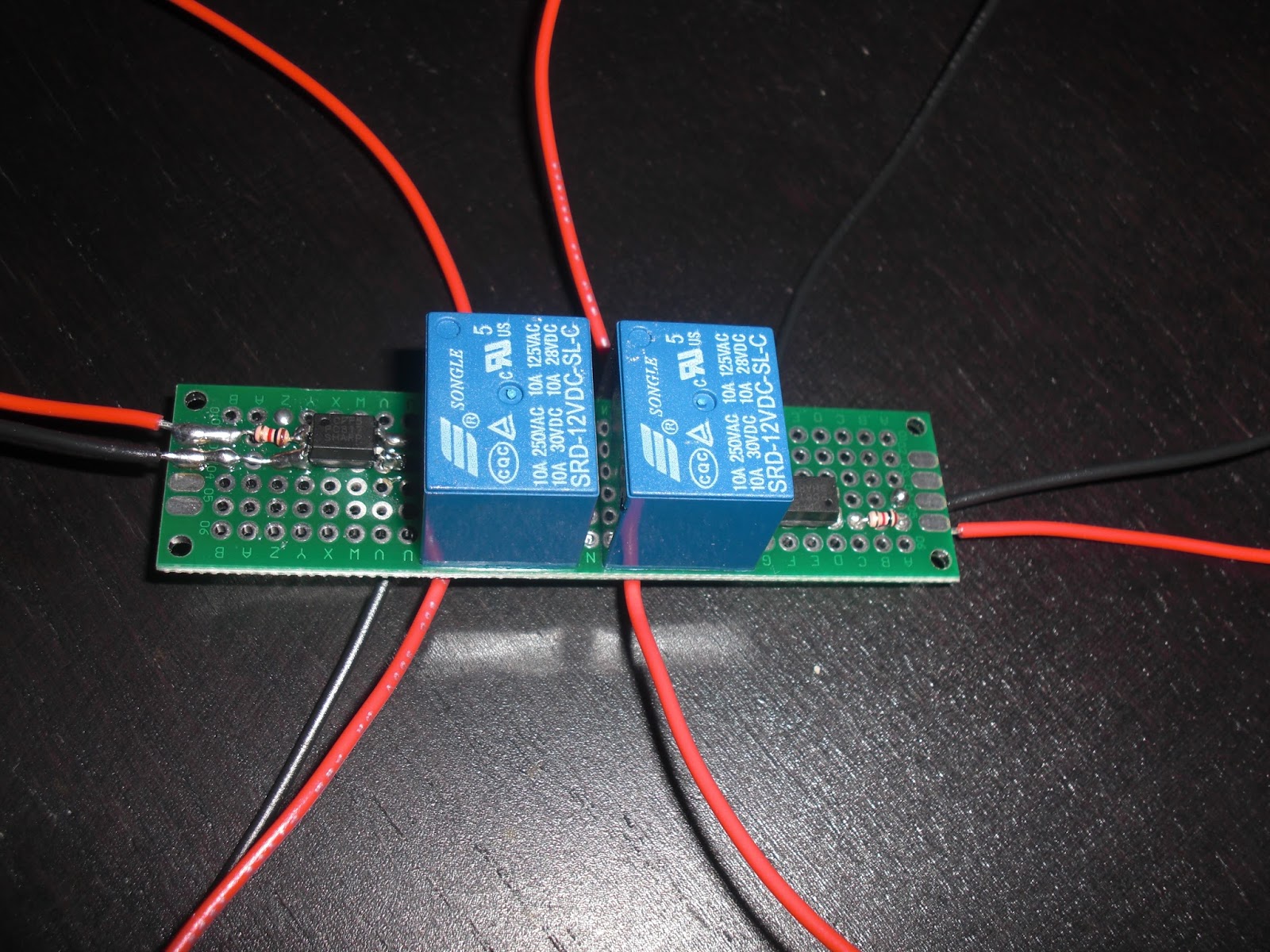
There we go, I have a small PCB board set up with two 12V Mini 10 Amp Songo Relays that are each activated separately by two Optocouplers. I only need one side of this board for right now to complete the wiring scenario I mentioned in my last post for turning on the Lower Console switch lights as part of the Knight Rider dash start up sequence.
The Red and Black wires you see coming in from the left side end of the board will ultimately be spliced into the wires that connect from the Voice Box to the last set of lights in the Top Countdown indicators, this way when the Knight Rider V.B. activates those lights a signal will be sent to the Optocoupler, activating my Relay and closing the power connection to the Lower Console switch lights. I did a little tweaking to my diagram so here it is again just so you can see my minor tweaks ;)

Wednesday, June 24, 2015

Mini Relays Board For Space Matt Buttons

I started soldering my mini Songo 12V Relays to the piece of Proto-Board I had for my Space Matt buttons yesterday. It was a bit of a pain to get the relays to sit straight on the board because the pins on the relays don't match up well with the holes in the Proto-Board, so they look like they sit at a slight angle. But it works and that's the main thing. So once this assembly is done I'll be able to wire this up to my Space Matt buttons and use some of the relays on the board to request a DTMF tone from the Knight Rider World Voice Box.

Friday, May 22, 2015

Rear Hatch Popper Button Relocation

Yesterday I took on the job of relocating my Rear Hatch Popper switch to somewhere a lot more accessible. One of the Switch Pod buttons seemed a logical choice. I decided to use the Switch Pod button on the Drivers window side of the Pod bottom right side button. (left)

The original location for the Rear Hatch Popper was located just above the car stereo next to the AC and Heater buttons. You can see a good example of this in this shot taken very early on last year near the beginning of my K.I.T.T. build. (right) With the Knight Rider dash design this area although not impossible is a little more difficult to get to. So my guess is that a lot of what is there will get relocated or hooked up to some sort of remote access. For now my Rear Hatch was my main concern as with the Taillight Blackouts I got from Knight Designs there is no key access anymore, K.I.T.T. does not have one. So in my case I was able to use the remote solenoid that was hooked up to the button under the dash.

In order to make this work I needed too take out the Rear Hatch button from the stock OEM dash and do a little work on it. I could have simply removed the button and used a couple of spade connectors with wires soldered onto them but I liked the idea of still having the original switch in place as a backup. So I drilled a couple of small holes into each of the switch pins near the base of the switch in order to thread my wires through. I then soldered on the wires to each of the pins and then drilled a couple of holes into the plastic ridge around the switch base. I then thread each of the wires through these holes, this way when the switch gets put back in the wires will not be "pinched."

I then wired the two switch wires I soldered onto the pins up to the Switch pins of a small NAIS SPST Relay that I installed into my Relay board under the stock OEM dash where the original gauge cluster used to sit. (right) This Relay was hooked up to to the Switch Pod Button which uses a positive pulse for the Relay as the ground connection is made on the Switch Pod Switch Side.

Now from what I understand the stock OEM Rear Hatch Popper switch already has a Relay in behind the dash so I may not have even need the Relay but when in doubt, I use one as it's sure not going to hurt, so basically I probably have one Relay on the Switch Pod activating the Relay for the Rear Hatch Popper, kinda funny but no big deal. It works very well as you can see in my Video from my last post ;)

Monday, May 11, 2015

Upper Console Wiring Scheme Updated Version

I have updated my wiring scheme for the Season One Upper Console electronics. Basically what I have happening here is my coloured set of four lighted mini-rockers (they go in order of Red, Blue, Red, Blue), the first two rockers are wired to my four Fog Lights through the SPST Relays I have installed under the stock OEM plastic dash. The third switch I will wire up to activate the Upper Consoles LED Displays, and the forth rocker I will have wired to activate the Count Up digital display. I figure this will make for a pretty good trip timer display.

I tested out my Fog Lights wiring yesterday afternoon just to make sure everything was working OK, all good, they work like a dream when the first two rockers are switched on, Red & Blue, the Fog Lights come on and the switch light comes on just as they should. There are other lighted coloured rocker switches that go up into that console that I have not ordered yet and I'm not sure what to do with those so they will be pretty much open to anything much like my buttons on my Lower Console although on my L.C. I do assign the Red and Green "?" buttons to my LCD and GPS screens in my Knight Rider dash. By using this wiring scheme I can effectively turn on my Upper Console electronics with just a couple of rocker switches installed into the console.

Saturday, May 9, 2015

Getting Ready To Wire The S-1 Upper Console

I have worked out a work in progress wiring scheme for my season one Upper Console. The way I had it wired before when I was using the season 3 Upper Console which didn't fit quite right, was I had a separate power wire running to each of the switches. For some reason I didn't realize that I only needed one power wire to run to the Upper Console and then just branch off of that so long as the wire is rated the correct AWG to handle the load. I'm still trying to figure out what all of the Season One Upper Console electronics pull power wise plus all of the lighted rocker switches for up there as well. Once I know that I'll have a far better idea of what gauge (AWG) wire to run up to the console. Like I say though in the meantime I have worked out a work in progress wiring diagram for this particular job. Seeing how most of the electronics are LEDs and the switches will be just going to activate the magnetic coils of SPST Relays I can't see the power load being that much, I could probably get away with an 18 AWG or even a 16 AWG gauge wire running from the pawer fuse block I have installed into the lower hush panel on the passenger side. I just want to be sure first before I go to the trouble of running any sort of power wire up there.

Monday, April 27, 2015

Alternate Space Matt Buttons Wiring Scheme

I was having some issues trying to work out a way to utilize each of my Space Matt buttons that I had made out of an old Texas Instruments Calculator. The problem was that the V.B. (Voice Box) random DTMF tone generator needs a ground pulse to activate a random tone, but with this type of button configuration where all of the buttons are connected to one wire (in this case ground) and the other buttons individual connections to that ground it was difficult coming up with a way to activate both a device and generate a tone through the V.B. So I came up with this idea. Seen here in my diagram I have two buttons wired to show a way in which they can all be wired in the same way to do just that, activate a device and generate a tone. In my diagram the ground connection through any one chosen Space Matt buttons will activate the relay's magnetic coil causing it's internal switch to close, in this case the needed ground connection from the V.B.'s DTMF tone generator to ground. It's a bit daunting having to use all of those relays but I can't think of another way off hand how to do this. Maybe those small "Songle" I think is the name of them relays would do the trick for this?

Example Image of "Songle" relay.

Ah Yes It Was a Busy Day!


After much fiddling about yesterday I was able to get the video board for the LCD screen for the PC installed into the Knight Rider dash. It took some fancy playing around with a few different configurations of how I was going to mount the electronics boards onto my Lexan plastic mounting bracket I made but got it done. Then came the wiring, I added a Molex connector to make installing the monitors setup much easier. Because that area of the dash stick out quite a bit I figured I should be OK with a shorter plug as I should be able to reach in under the dash and plug it in.

You can see in my various shots how I have connected up and installed the video board for the PC LCD screen. See how I mounted the little extra board that has the small tactile buttons for controlling the LCD screen settings, those I have added extra wires that I'll run to the Space Matt buttons, bottom row most likely. That way the LCD screen can be adjusted if it ever becomes necessary to do so.

The GPS screen's board I had already installed onto the back piece of Lexan plastic I had cut to fit snugly into the back of the fibreglass monitor frames, so that little board was pretty easy to deal with as it was originally all packed tightly into a plastic enclosure when I got it.

Here you can see the monitors finally installed. Please excuse my mucky finger marks all over the GPS screen, lol need to clean that ;) The two screens look different because the GPS screen is a touch screen whereas the LCD PC screen is not. I may change that, not sure yet. It kind of depends on so many things. ;)


Saturday, April 25, 2015

LCD PC SCREEN AND GPS TO POWER SWITCHES

I have a wiring plan for how I am going to hook up my two monitors for the Knight Rider 2 TV dash. The GPS unit actually gets stepped down from 12V DC to 5V DC with a step-down converter I got off eBay for  few bucks. The LCD monitor for the PC (Computer) takes a 12V DC in but I believe it gets stepped down through the video board. But basically I am going to use my Lower Console buttons to power up the LCD screens. My thought is the green "?" buttons I'll assign to the GPS unit and the red "?" buttons I'll have power up the LCD screen.

The PC LCD screen has an additional small board with 5 mini or micro tactile buttons on it that control the monitor settings. I have not yet put my Multi Meter on those yet to see how they are hooked up but my initial thoughts are to extend the wires and use some of the calculator buttons in my Lower Console to control those buttons. I'll do some testing and see if that is possible.

NOTE: In my diagram above, this is a very conservative way to do this although the monitors fall well below what the lower console switches are rated for so the Relays are not really needed. I have them in place should I ever decide at some future time to use those switches for something else that draws way more mower than the switches are rated for such as Amps or Fog Lights. Anything that draws more power than what switches are rated for you definitely need to use Relays.

Sunday, April 19, 2015

Installing And Wiring My Space Matt Buttons

"Buttons, Wires and Connectors, Oh My!"

Well I installed my make shift Space Matt buttons a little differently that I wanted too. I was going to cut out my rectangular hole a little bigger so as to sink the Space Matt buttons array into the hole so it would sit flush, but I'm a little hesitant to do that because the hole is cut to the size of the USB Space Matt Keyboard buttons that you can get from Knight Rider World, and like I say these may just be temporary buttons for me to use until I get around to ordering the USB buttons. Of course me doing it this way means that my plastic overlay I made is a little too thick for how I have the Space Matt buttons placed into the console as in they sit a little deeper down. I may make a thinner overlay out of some metal stock I have kicking around, I'll see what ends up looking good.

I had drilled in a large enough hole into the top of the fibreglass console to be able to thread in my wires for all of the buttons. I had to add a little more length to the wires so I would have a little more room to put in my Molex Connectors. I had to get a couple of 15 Pin Connectors as the electronics place did not have anything bigger. That's OK though, it just means having another connector sticking out of the wire loom ;) Each one will be clearly marked so they can't get confused so no biggie.

I have the one wire that connects all of the buttons together on the far side of the Molex Connector and then the 4 rows of individual wires for each button connection using up the remaining pins of the connector. This way I can organize them on the connectors in rows from top to bottom. Here in this picture on the left you can see I have started putting together the wires into the connector, I have the main buttons feed wire in place and the first top row of buttons wires in place, now to complete the connectors by following the same format. ;)

Wednesday, April 1, 2015

Lower Console Installation Challenges


On of the major challenges I am currently facing with the installation of my lower console is the huge "Rats Nest" of wires there are for all of the switches, it would be a lot less wires if I was never going to have any plans for the switches and just wanted the pretty lights lol, but I do want to do something with the buttons eventually so I most definitely want it all set up for that eventuality ;)

After a test fitting I found I had to take out the shifter knob so I could remove the forward OEM stock plastic console cover to thread my wire harnesses through. Even with that the huge "Rats Nest" of wires was still making it difficult to get the wires into the hole I had cut out. So I had to try to minimize the amount of "Chunk" with the wire "Rats Nest" even as well bundled and organized as it was it was still a "Rats Nest" lol
After going another test fitting and trying to get the now minimized "Rats Nest" stuffed down into that hole it was still difficult. I'm almost thinking that a smarter idea of installation might have been to have taken out the entire centre console, put it up on my work bench and installed it directly to the console. I must admit it might have make running the wire harnesses through the console easier and then I could have tied them off to the side of the console. Something to consider if I ever make another Knight Rider car in the future.

In any even a little more thinning out of the wires on the console will be in order and then I should find it easier to stuff the wires into the hole. I wonder if in the T.V. show if they only had the switch lights hooked up as I can see them having a real fun time with putting in some functionality by running the extra wires... I know I sure am lol ;)


Sunday, March 29, 2015

Overview Diagram For Wiring My Lower Console To My 12 Position Fuse Block


Here is an overview diagram of my initial plan to wire my lighted lower console switches to my 12 position fuse block which is rated at 105 Amps Max, although I'm going to keep it at an even conservative 100 Amps Max. In this diagram you can see I have marked each switch circuit for what the switches are rated for and times that by the number of switches. These are simply controlling SPST Relays, I'm using a 10 AWG power wire to link up all of the switches, this wire is pretty short and then goes into a nice 16 AWG wire that is a little over 6 feet to reach the fuse block I have installed under the passenger side. According to my wiring charts it should be WAY more than I need to handle any load the lower console may consume.... even less if I eventually switch out the bulbs to LEDs. As near as I can tell this should be good.

Monday, May 26, 2014

24 Pin Connector Installed

I have installed the first half of the 24 Pin Connector as part of my Knight Rider 2 TV dash install. Took a while to solder the wires to each of the 24 Pin Connector wires and then heat shrink tube each wire to make sure they were properly insulated. Once done with the connections I had to make new labels for each wire closer to the connector plug so I will be able to identify each wire coming from the dash. There are a few of them I'm pretty sure do not get used but just on the outside chance that one day they might get used it will be nice to know what they are so I'm glad I have taken the time to make sure that I have identified each of the dash wires.


I had to pop out to Canadian Tire to pick up some 3/4" wire protector to wrap the wires up into a nice harness. I zip tied the harness to the plastic of the dash so it will not move around much. I'm not sure where it will be best mounted from there? What I will need to do is install the other part of the 24 Pin Connector to the Knight Rider dash and see where the best location for securing the wire harness will be. For now I just have the end of it draped over the steering column till then.