Showing posts with label relays. Show all posts

Monday, April 18, 2016

Relays Labeled

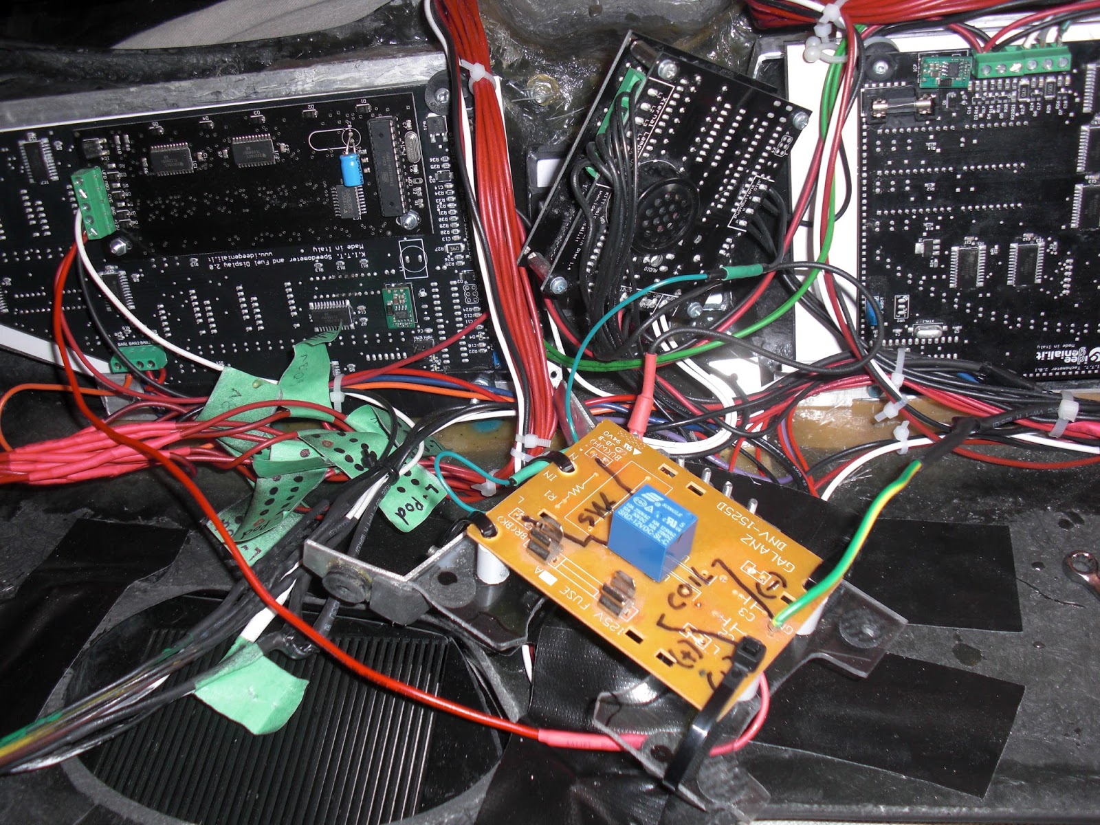
I have all of the 16 Channel Relay Modules Relays controlled by the Arduino Mega labeled so that way I can know what they are at a glance even though I also have the wires going to each on the low voltage input pins labeled too having the tops of the relays visibly marked helps things a lot too. I figure this will make the job of connecting the switch side of each 10 amp Relay up to it's corresponding device a lot easier. The funny thing is that many of the Relays I don't even have a device to hook up to them yet, but it's sure nice knowing that the initial framework is all in place and ready for very easy hook up when I do eventually have the devices to hook up to them.... and that my friends saves a boat load of work to do in the future right? ;)

Saturday, April 16, 2016

A Smaller Relay Module

Some of you may recall way, WAY back when I first started my dash install I had a series of NAIS relays mounted onto a piece of Lexan plastic that I installed in the area where the old Gauge Cluster used to be. If not maybe this image might refresh your memory a little ;) One of the reasons I had done it this way was,
one: I was not sure how many Relays I was going to need,
two: I was not really sure how to go about hooking up any devices I was going to want to install which also meant not knowing how many Relays were going to be needed too. So needless to say I was a little all over the map in some areas and fairly indecisive as to what direction to go in. So I went with the idea of;
"I would rather have too many than not enough."

Eventually as this project progressed and I started developing my own Dash Software (Knight O.S.) things started to become a little more clear as to how many and what sort of Relays I would need. So I pulled the old Gauge Cluster housing out of "Mothballs" and began modifying that to house the Arduino Micro Controller and some Relay modules.

I took about 6 of the NAIS Relays and soldered them onto a piece of Proto-board along with screw terminal blocks that will serve and the low voltage inputs to trigger the magnetic coil of each Relay. I then soldered on some 18 AWG wire for the outputs on the switch side of the relays. I soldered some pretty thick tracks onto the photo-board to make sure I had more than enough to drive any current the Relays are capable of, probably went a little "over kill" but what the heck, you know me..... lol or you should by now. ;) I took the extra precaution of reinforcing the wires soldered onto the photo-board by applying a good coat of fibreglass resin on the tracks side of the board and the top side. rest assured those soldered connections are going nowhere. ;)

I then took a strip of high density foam rubber that has a sticky back side and applied that to the track side of the board. (See Left)

I then mounted the newer more compact relay module into the Gauge Cluster housing like this. (See Right) 
With that all hooked up in there nice and neat that will give me 6 more additional Relays to use if I need them. I still need to mount in the 5 pin Relay that is used for the Headlights & Running Lights, but I should be able to work that into this scenario. I'll keep you posted on what I do for that.

Wednesday, April 13, 2016

Arduino Module

Lots of soldering wires today for the Arduino Module to control the 16 Channel Relay Module. There are lots of connection still to have wires soldered to when I get another Relay Module. As it is it's pretty crowded with wires and I have that project box pretty stuffed, but neatly stuffed. I'll take to top off in a later post and show how it's all put together. Depending on how much stuff you want our Knight O.S. software to run will really determine how stuffed your project box will be. My guess is that if you wanted every device hooked up you would need a bigger project box to make room for all of the wires as they take up a good deal of space.

As you can see I have my wires for each of the Arduino pins that they are connected too so I can track which one goes to which of the Relays on the 16 Channel Relay Module. If all goes according to plan I may very well be able to install this Arduino Module and the 16 Channel Relay Module into the blue plastic Gauge Cluster housing that I spent the better part of this morning cutting out all of the "greeble" to make usable space inside of the old Gauge Cluster housing. That was a time consuming and messy job that involved lots of cutting with my Dremel Tool.

Here is a shot of the old Gauge Cluster housing all cleared out to make space for the Arduino & Relay Module. I should be able to mount those other Relays I have installed under the dash into this thing too and it should make my install a lot cleaner of a job. ;)

Here is a shot of the Arduino Mega with the Connections "Hat" I made with the wire connections soldered on for the 16 Channel Relay Module, LDR Sensor, Temperature Sensor and Compass Module & Compass LEDs. As you can see if one wanted to hook up all of the other pins you would probably need to make some holes in the sides of the Project Box or use a bigger Project Box to contain it all. But even a bigger Project Box will still fit quite nicely into the blue plastic Gauge Cluster Housing area.


Saturday, April 2, 2016

Prepping For Final

I can start working on minimizing the need for the Breadboard now especially after I make a Optocoupler board for the button inputs to the Arduino so that Switch Pod or other buttons can be assigned to trigger certain screens in our Knight O.S. interface like the Environment Scan Screens, Manual Override, or Telephone Tap Simulator Screen. These can be any momentary button which makes either the Switch Pod, Space Matt Buttons or Possibly Lower Console Or Upper Console Buttons usable for this so long as they are momentary buttons.... heck even if they are not momentary buttons I have a circuit that allows Latching Buttons to generate a short pulse to simulate the function of a momentary button. So the option either way is there.

I currently have plugged into the Breadboard a bunch of wires that are going into the Arduino ports that are coded for stuff but not actually hooked up to a Relay Module yet. I need to get a 2nd 16 Channel Relay Module and modify that one just like the one here, but for now that is kind of optional for me as most of the main functions are routed through the first Relay Module. The 2nd Relay Module would be more for all the cool extras. Although you can mix and match and assign ANY of the outputs to whatever Relay you want so for example if you don't use the Auto Doors but are going to use the S.I.D. function all you would need to do is connect up the stuff you are using, The interface would still go through the motions just without the Relay hooked up it would not actually perform the "Physical" function.... but I think you get that.

The other thing I can do now is hook up the LDR and Temperature Sensors, I think I am going to install those two up into the Upper Console as that seems a logical place. The LDR Sensor I can mount so that it is facing forwards out the front part of the Upper Console that way it will get it's light values from whatever comes through the front Windshield. The Temperature Sensor seems to make sense to me to be up in the Upper Console as that way it is away from the Heater and Air Vents which I think would cause inaccurate readings to occur, that's my thought on it anyways, but I can see that being on of the best places. The Sensor for the Compass however is a whole other animal right now so not sure about that one. Getting Closer though :D

Thursday, November 19, 2015

Dash Auxiliary Power Button


I have a better way of hooking up my dash auxiliary power button as right now the way I have it is a bit daffy and I'll explain why; The scenario works but what happens is that say I have the auxiliary power button turned on and I forget that it is on and then I turn over the cars ignition, well when I turn off the ignition key the car will keep running because power is still being supplied through the lower consoles auxiliary dash power button being turned on, I would then need to switch that off in order to turn the car off. This way is much better because that can't happen as the dash can only get it's power from one source or the other via the relay and not both at the same time which is how I currently have it wired.

Sunday, October 25, 2015

A Better Relays Board Installed

It took me a little while to install he new relays board I made with Rectifier Bridge Diodes before each of the relays in order to cure that problem I was having with the SFX module I had put together. I had to do a fair amount of shuffling things around on my stock dash to make things fit right. (left).

You may recall from earlier posts when I was working on my Voice Projection Unit that I had the on/off button hooked up to a Step Relay that was located about where my new relays board is now. What I ended up doing was moving the Step Relay to the same location as the on/off button for the V.P. Unit and mounting it behind the panel that the button is mounted too (right). I also made up a small Rectifier Diode Bridge module with terminal blocks that I could easily wire up to between the on/off button to the Step Relay and mounting that in behind the panel as well. I like it a lot better now because when you press the V.P. button the loud click from the Step Relay is right behind where the switch is located and not on the other side of the dash like before, so in many way it makes more sense this way.

Friday, October 23, 2015

A Better Relay board


This is a much nicer relays board than my last one which was more for experimentation more than anything just to see if certain things were going to work the way I wanted them too. This new one I put together is better laid out, has more relays on the board and more terminals for the DTMF request from the Voice Box. The board is a little shorter than my old one width wise but a little higher height wise but given that it better made and has more on it I'll be able to work that under the passenger side of the dash a lot easier than my last set up. This new board also has Rectifier Diode Bridges built in before each relay so this will eliminate the problem I was having with switches that activated relays interrupting my SFX module when the relays were switched off. I'm a little fuzzy on how that works exactly but it works and it cured the problem so that is what counts. ;)

Friday, August 7, 2015

Bread Board Experiments


Yesterday I was experimenting around a little with the Darlington Driver 50V / 500mA Transistor array chip model number ULN2803A. I wired up a simple circuit on my Bread Board with 2 mini Songle 12V 10 Amp relays, some resistors, micro tactile buttons, wires, a single red LED and the project 2 LED flasher circuit that came with the starter kit I got.

Now this is really simple setup using the Darlington Transistor
array chip in that my micro buttons (in this case) are switching on a stepped down 9V current through the resistors to simulate a low current input to the Darlington array chip. This is ideal since I intend on using an Arduino to control input signals to the chip, and Aduino uses a low 5V output, same as a USB device. On the other side (Outputs) of the Darlington array chip I have the necessary voltage needed to trigger the magnetic coils of the mini Songle 12V Relays and as you no doubt already know that on the switch side of the relay I can have anything I want to activate up to 10 Amps, which is a lot of current. I can use higher rated Relays if I need to power anything that requires more than 10 Amps.


So in the experiment yesterday I have it so when you press once of the micro buttons the single red LED turns on through the switch of one relay and when you press the other button the small 2 LED flasher circuit turns on through the switch of the other relay. Now keeping in mind that for a low power input of 5V (USB) I would not need the resistors in front of the input pins on the Darlington array chip, this makes for a very small space saving potential PCB board to control stuff from my dash software I have been developing in Unity 3D. I'm planing on using the Arduino because so far it's what I have found that communicates well with Unity 3D both as a means of controlling from the Arduino and sending information too the Arduino.

Monday, July 27, 2015

2 Low Input to 2 Higher Output Relay Board


I did up a quick diagram of the little PCB board I made with some great help from Andrea lannaccone from Face Book. There are smaller ways to do this but this is pretty small too, you can do this type of switching with a Transistor too. For what I am doing with my Top Countdown Indicator lights to activate the switch lights on my Lower Console I only need one side of the board but there was room on the board to have the same ability twice so at least I have an extra setup for should I need to do something similar again. :) 

PCB Board Installed

I installed the small PCB board later today just overtop of the other Relays board I had made a few weeks ago. I have the power wire (blue) going from the fuse panel I installed under the passenger side Hush panel into the magnetic coil and switch terminal of one of the mini Songo 12V 10 Amp Relays, this will supply power to energize the coil and provide power to one side of the Relay switch. The other blue wire you can see coming out of the top of the Relay is the 2nd power wire on the other Relay switch terminal, this wire goes into my Lower Console to supply power to the switch lights. The Relays switch will connect the two completing the circuit. The two input wires Red and Black that connect to the Optocoupler I have going into a couple of spare sockets I had available on my Molex connector for my LCD and GPS screens. Those will provide the low input signal to activate the Optocoupler once the Countdown indicator reaches it's last light, this will in turn activate the Relay making the connection as described before. Tomorrow will be the big day I test this out so if all goes well I'll be doing a video to demonstrate the final effect.

Tuesday, July 7, 2015

DTMF Tone Request Experimentations


In making sure that I well isolate the Voice Box's DTMF tone request from any momentary buttons I have I figured I would rig up a mini Songo 12V Relay very close to the Voce Box. Now what happens here is that when a DTMF Tone request is called by any momentary button I have hooked up to a wire that I am calling "DTMF Tone Request" THAT wire goes to the magnetic coil of this mini Songo 12V Relay's Ground (-), the other side of the magnetic coil goes to 12V (+). So this then trips the Relay's internal isolated switch which I then have connected to both the Voice Box's Ground (-) and also the DTMF Tone Request port. You will have to excuse my somewhat over sized piece of PCB board it was all I had kicking around that I could use to mount this small relay onto and connect wires too. I'll most likely change it later when I get some smaller pieces of PCB Proto-Board. The wires from the Switch Pods that request the DTMF tone I just have going directly into the Voice Box's DTMF Tone request port.


Now the other part of today's fun was to wire up my Relays board for some experimentation just to make sure that I am understanding correctly just what is going on with this thing and how it interacts with my buttons. All of this stuff gets pretty complicated if you are new to electronics like me. ;) My latest video that I posted to my blog explains best and visually how I have it all hooked up. But basically the Ground pulse buttons from my Space Matt buttons go into the ports on the board that connect to the Diodes, they connect to the DTMF Tone Request wire and also to the individual relays on the board. Each relays gets it's own ground pulse from each of the Space Matt buttons activating the Relays internal switch which I can hook up to any device I want to activate, in my case 5 of the Space Matt buttons are simply activating buttons that control the setting for my LCD screen. Although I have not yet hooked it up, a 6th button will cycle the Message Centre while producing a DTMF tone with each press of the button. The rest of the Space Matt buttons I don't have plans for just yet.

My Voice Projection unit activation button is wired up the same way as the Dash Power Button and makes a connection to ground to activate the Step Relay, this one was a little more tricky. You can see in the image above (middle left) that branching off from the wire that comes from the Normally Open terminal of the V.P. power button that I have placed a Diode in-line connecting to the DTMF Tone Request block.... which I moved onto the back of my Relays Board. Without the Diode in place the Space Matt buttons would activate the Step Relay for the Voice Projection unit as well, not good, so the Diode sure takes care of that as it only allows current to travel in one direction... taking me a while to get the hang of that but it works and it's cool... gotta love electronics ;)

So now with all of this in place I'll have to test it out on the Voice Box once the replacement I.C. Chip 01 comes in the mail. If everything works out well, and so far I can't see what not as a Relay does what a Relay does ;) But as I say if all goes well I can look into experimenting with the Optocouplers when they arrive and see if I can make a set up like this that takes up a lot less space. This would be fine if I only wanted to use a small amount of my Space Matt buttons but I can see eventually wanting to use more down the road as I trick out K.I.T.T. with more cool gadgets ;)   


Wednesday, June 24, 2015

Mini Relays Board For Space Matt Buttons

I started soldering my mini Songo 12V Relays to the piece of Proto-Board I had for my Space Matt buttons yesterday. It was a bit of a pain to get the relays to sit straight on the board because the pins on the relays don't match up well with the holes in the Proto-Board, so they look like they sit at a slight angle. But it works and that's the main thing. So once this assembly is done I'll be able to wire this up to my Space Matt buttons and use some of the relays on the board to request a DTMF tone from the Knight Rider World Voice Box.

Wednesday, April 29, 2015

Progress, Progress, Progress!

Wow! What a busy day yesterday, at first I didn't feel like I was getting a lot accomplished but at the end of the day I realized just how much I had done, soldering of wires to connectors for connecting to Relays in the dash, hooking up ground connections, putting the shifter knob back in after testing all of the wires running through to my Lower Console, hooking the green and red "?" buttons up to Relays in the dash for turning on the LCD and GPS screens in my Knight Rider 2 TV Dash, and then putting together a video, wow! more done than I thought :)


Here on the left you can see a shot of the shifter knob reinstalled and I even added the "Knight" logo that I got from Michel Hageman a fellow Knight Rider builder friend on Face Book. I even got around to ordering the S-1 Upper Console electronics from Knight Rider World later on yesterday too.

Here's a shot of me fiddling about with all of the wires inside of the car. It's a good thing I make all of those diagrams because all of that wiring gets very confusing after a while and sometimes hard to keep track of. K.I.T.T. is going to need a Manual once he's done lol. Which kind of reminds me that I'll need to do a new diagram of how I have hooked up my Lower Console switches to power my LCD and GPS screens as they are being done through a couple of small NAIS SPST Relays switching on the power side and not the ground as I have pictured in my last diagram.


Here is a couple of shots of my Lower Console installed. You can see how I have my mounting screws going through those side "wings" (top left) I had  glassed onto the console when I made the modifications from a console that covered the e-brake to one that allows the brake to be used, which in some states and provinces is law! if your car is equipped with one it has to be accessible.


Monday, April 27, 2015

Alternate Space Matt Buttons Wiring Scheme

I was having some issues trying to work out a way to utilize each of my Space Matt buttons that I had made out of an old Texas Instruments Calculator. The problem was that the V.B. (Voice Box) random DTMF tone generator needs a ground pulse to activate a random tone, but with this type of button configuration where all of the buttons are connected to one wire (in this case ground) and the other buttons individual connections to that ground it was difficult coming up with a way to activate both a device and generate a tone through the V.B. So I came up with this idea. Seen here in my diagram I have two buttons wired to show a way in which they can all be wired in the same way to do just that, activate a device and generate a tone. In my diagram the ground connection through any one chosen Space Matt buttons will activate the relay's magnetic coil causing it's internal switch to close, in this case the needed ground connection from the V.B.'s DTMF tone generator to ground. It's a bit daunting having to use all of those relays but I can't think of another way off hand how to do this. Maybe those small "Songle" I think is the name of them relays would do the trick for this?

Example Image of "Songle" relay.