Showing posts with label 1982 firebird. Show all posts

Sunday, July 12, 2015

Headlights Switch Relocation

 I relocated my Headlights and Parking Lights switch onto that piece of Dash Trim that fit along the lower part of the stock OEM dash just below where the Gauge Cluster used to be. I had to do some cotton and modifying of the plastic part to make it fit into the space with my wire looms but got it to eventually fit in there nicely again. The next step was to make an aluminum bezel to fit over the Headlights switch. I cut out a piece of aluminum and cut out a hole the same size and shape of the hole that was in the stock OEM bezel that held both the Headlights and Dash illumination dimmer switches. I sanded it down (top left) and then marked where I would need to bend it (top right). If you have a "Metal Break" bending the aluminum is easy if not you can do what I did and use a Vice and a hammer.

I then cut out a hole in the plastic dash trim (left) big enough for the Headlights Switch and then fit the switch into place (right). I put the plug back on the end and test fit the whole thing back into the dash. I had to use my Dremel to do a little cutting in the stock OEM dash to make the plug fit into the space better because it's a big fat beast of a plug but with a little cutting work it can be made to fit nicely to the hole. I fed the wires from the plug in through the hole and down in through the underside of the dash, that way I can solder them the the other wires I have going into the wires that came out of the area of the stock OEM dash that the original plug was attached too. Basically all I am doing is extending the wires and relocating the switch to somewhere more convenient.

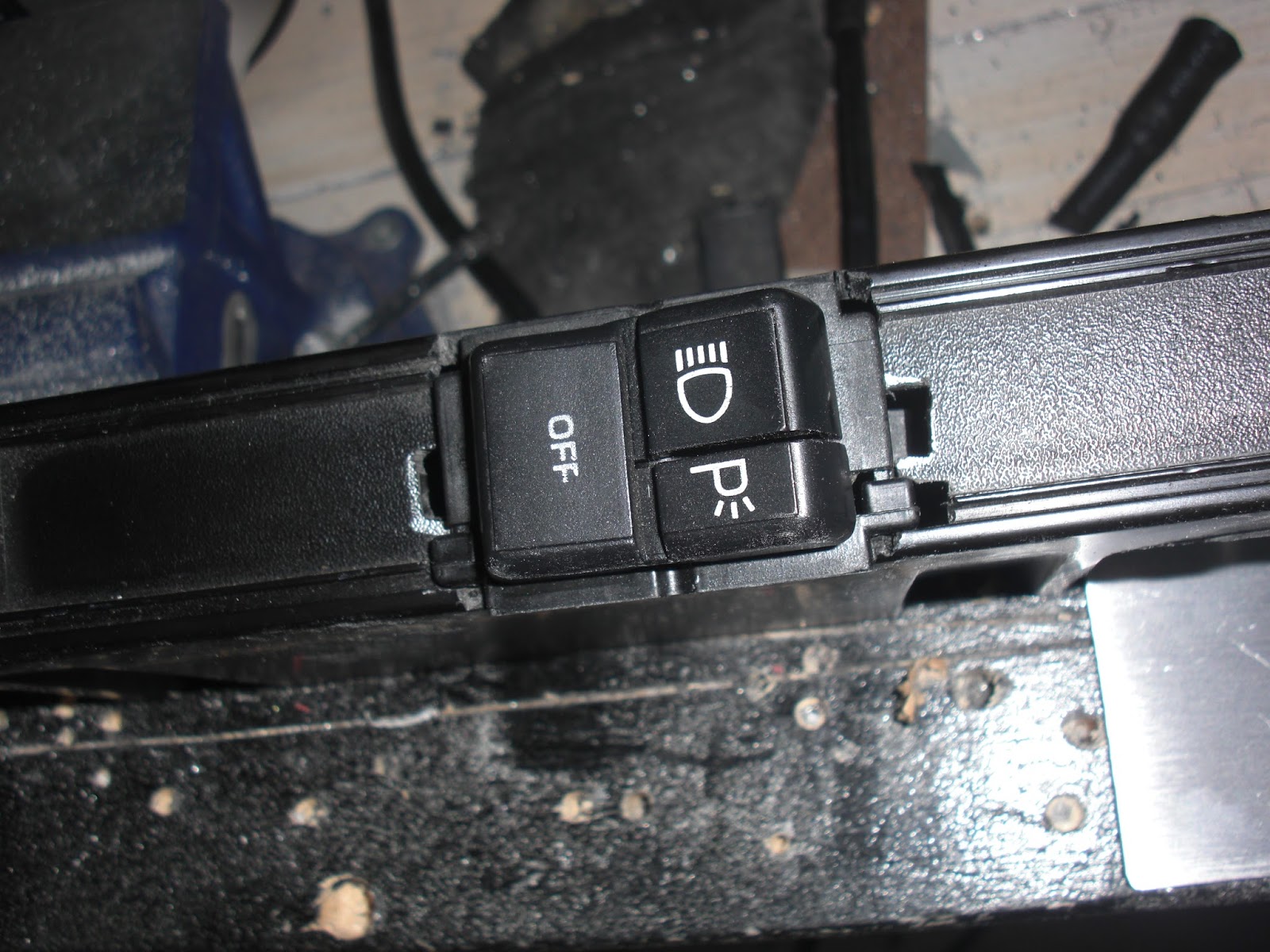
After bending the aluminum bezel into the right shape I fit it into place over the Headlights switch (left) and drilled in four holes to screw it onto the dash trim with. Next I sanded down the aluminum bezel one last time before giving it a good cleaning before painting it (right).

Once the paint was dry after baking in the hot sun for a few hours (left) I then attached the bezel to the plastic trim with four small black screws (right). With that job finally done the last thing to do was to attach the whole assembly onto the stock OEM dash and give the Headlights a test, something I was pretty sure I had never done since the car arrived almost two years ago. WOW! two years ago!! It's sometimes so surreal thinking about that, the time has gone by so fast and so much has been done on my K.I.T.T. Project.

Here is the final assembly in place, it's not screwed in yet as I have a lot more mucking about to do with wiring and such but it's in place and has been tested out, check out the two videos in my previous postings to see how that turned out. ;)


Wednesday, June 24, 2015

Cowl Induction Hood Modification

I cleaned up the solenoid and actuator arm that controls the air flow flap as it had a little bit of surface rust on it. I cleaned off all of the rust with a gel rust remover, cleaned it up and then painted it black. Left the parts to dry overnight before re-assembling it back together.


Next step was to make some sort of bracket or mount that will hold the lights and allow air to flow freely into the opening. I made this bracket out of some stock aluminum that you can get from the metal centre of most hardware stores. I cut it to fit inside of the air induction unit and cut tabs to mount my light on.

The basic idea here is to do something very similar to what this other Knight Rider car builder has done with his air induction unit. I have added an extra tab that I figure will be a great place to put my "Check Engine" light at the far right of the mounting bracket.


Wednesday, May 27, 2015

Modifications to the Front Ground Effects

I figured now was as good as any time to do something with my Front Ground Effects, they had been kind of just hanging loose for the better part of over a year after I had installed my Knight Rider Front Nose. At first I was not really sure what to do with them and I was not finding a lot of information out there as to what other people within the Knight Rider Community were doing with theirs. Although about a week ago I did see one fellow on Face Book post what he had done which involved doing some modifications to the Front Nose fibreglass itself. I was not sure I wanted to go quite that far as from what I could see from looking at the underside of my car that it looked like just making a few modifications the the Ground Effects themselves with my Dremel tool would be the simpler solution. So after much "humming & hawing" about what to do I decided to go with this idea.

First thing to do was jack up the car so I can get my tools under there to work. Now on the inside of the Ground Effects there is a ridge of plastic that needed to be trimmed off so that the Ground Effects panel would fit more flush with the bottom part of the Knight Rider Front Nose. I used my Dremel tool to trim off the ridge of plastic area I have circled in the the image on the right.


Now on the outer most edge of the Ground Effects panels you'll see another ridge of plastic that also needs to be trimmed off. If you press the Ground Effects up close to the bottom of the Knight Rider Front Nose you'll see exactly where to trim in order to make them fit flush with the bottom of the Front Nose. You can see I have also used Trim Fasteners to secure them to the Front Nose. I needed to use my Step Drill bit to widen out the holes in the Ground Effects for the Trim Fasteners and then use a drill bit to drill holes into the bottom of the Front Nose big enough for them to fit snugly into. Like I say I'm not sure if this is how a lot of people do it but this is just what I did in order to get my Front Ground Effects to fit onto my Knight Rider Front Nose.

Saturday, November 22, 2014

Test Fitting The Lower Console With The New Mounting Tabs

After I had finished fabricating the mounting tab on the drivers side of the lower console I took it out to the car to do another test fit to make sure that the two mounting tabs were going to work well together. I figured they would but sometimes you never know with this stuff until you do a test fit, there could have been some adjustments that still might have needed to be made. Fortunately it fits great.

I think the mock panel on the top of the stock OEM console make need to be cut out, I say "Mock Panel" because I don't think it is a real panel held in with screws, just made to look like it does. Firebirds seem to have a few "Mock Screws" in them. I'll examine it in closer detail before I go and drill my side mounting holes into the stock OEM centre consoles sides.

In the mean time I can begin the long process of adding layers of primer to my modified lower console this way I can see better where there are any surface flaws that need to be sanded and filled. Once i have it all primed and smoothed out I can begin to look into working out how my switches are going to get mounted onto my lower console. I have a non functioning set of space mapping buttons that I had bought very early on in my Knight Rider Conversions Project but over time I have become dissatisfied with them given that there are plenty of working versions of the same type of buttons available, and on a personal note I want to make as many functioning aspects of my K.I.T.T. as I possibly can.

Saturday, August 16, 2014

Headlight Covers Repainting

I started painting the headlight covers since they had some light chipping along the front edges where the original white paint was starting to show through. I was going to take them right off and do both sides but then determined it would be just as easy to just mask them off from the rest of the car and prime and paint them in place.

First I needed to prep the surface of the covers by going over each one with scuff pad. I know a lot of people use the grey scuff pad for this but I find with the sand-able primer I can get away with using the red scuff pad, its a little more or a coarser grade but the primer fills in the surface really well.


Once all sanded or I should say scuffed up it was time to mask off the covers from the rest of the car. Normally I use plastic drop sheet material for my masking but for small stuff like this and considering that it was an under the hood kind of area news print is more than good enough. I'm actually using flyers which are a little thicker paper.

Once all masked off it was time to give each headlight cover a good cleaning with some isopropyl alcohol to clean up and grease and dust. Then a going over with a tac cloth.


Once the primer was dry it was time to paint. I let the paint fully dry over night before putting on a few coats of clear coat. I'll let that dry over night as well so that way the clear coat is good and set before the wet sanding.

They look pretty shiny already with the clear coat applied. They will look even shiner when they are eventually wet sanded and then polished.


With the hood open I took the time to paint the edged of the scanner bar a matt black so it does not stick out as much. I just used my fine brush and brushed on some model paint as it's just a small area and that paint is pretty durable. I may eventually make some kind of plastic covers for those end pieces just to make the ends look a little neater, I'll see what I come up with and what looks good.


Monday, August 11, 2014

Front End Nearing Completion

K.I.T.T.s front end is nearing completion. I still have a few things to do but as you can see it is getting closer and closer to being done. You know I was amazed going through my photographs the other day at just how far I have come along with this project. I mean for a guy with absolutely no prior automotive experience I feel I have done pretty darned good all things being considered. I am well on my way to achieving a life long dream of owning my very own Knight Rider car.


I took some of the rubber that was on the original GM flat hood that came stock with my '82 Trans Am and cut some to fit across the top of the scanner between the hood so it helps close up the small gap at the top of the scanner. The rubber also acts as a bit of cushion between the top of the scanner and the front of the hood.


Here is a shot of K.I.T.T. with his new Turbo Hood finally on and his scanner working.

You can see I still need to do something with those front ground effects, not yet sure if I am going to use trim fasteners to attach those to the underside of the front nose or if people just take them out. I'm still looking into that.


I think I figured out the issues I was having with how the air cleaner assembly was attached. My guess is that they must have done some kind of engine modification that bypasses most of what the air cleaners original function was as that small short hose was clearly NOT attached to the Carburetor, where it would have gone was sealed up with a short piece of rubber hose with a screw in the end. So I figured OK if it was working fine like that before why mess with something I don't understand I'll just attach the new shiny one in the same manor. I'll get someone with much more automotive skills than me to have a look at it later on when I can get a chance.

Wednesday, July 2, 2014

Turbo Hood Waiting

I took the precaution of wrapping up my edged and top with bubble wrap, foam padding and cardboard because the route to the garage is a little precarious and anything can happen between my back room and there. ;)

All I need now is someone to help carry it out and gel me hold it steady while I bolt it onto the car. With a little help it's a 10 minute job at best. I've been waiting out our crappy weather for a nice day to do this little job too.

On another note, my Marine speakers should be arriving today so I'll be able to hook those up to Brenon's LED scanner box after I place them into my custom enclosure that I'm making using some PVC plumbing pipe. That should be fun. Once that's done I should be able to re-hook up my batter and test out the electronics that I have installed into K.I.T.T. so far.... keeping my fingers crossed that I don't turn out to have any dodgy wiring on my hands... :/ I have tried to be a careful as possible and have checking things numerous times to make sure I have done a good job.... but even still, being new to this I can't help but be a little apprehensive about it :/

Friday, June 6, 2014

June General Updates

Some general updates for stuff I have been working on over the last several weeks just in case you were beginning to think that I have been slacking.  I patched up the antenna hole in the fender with some metal screen patch and some Bondo. I accidentally stuck my finger in it before it had a chance to fully cure so I had to skim it over with a little extra Bondo once the first application had fully cured. Primed and painted it. It just need some wet sanding when the paint has had a chance to cure. Maybe another light coat of paint after the wet sanding, I'll see where I'm at when that is done. Once wet sanded and eventually clear coated you will never know that there ever was an antenna hole in the fender.

I have decided that the whole car does not need to be painted just re-touched up here and there. I have found that the Duplicolor Universal Black seems to be a perfect match for the nice deep rich black currently on the car so I might as well just touch up where needed as it's mostly a few minor rust spots along weather stripping and a few paint chips here and there. I did have to re-do most of the rear spoiler, mostly just a few paint chips along the edges but I did discover that the underside of the spoiler was given the same kind of paint job treatment as the rear taillights compartment, just not cleaned up very well so the paint did not adhere very well to the original paint surface.

I have finally started to get the first few coats of paint on the front nose. I'm doing it with Duplicolor Universal Black in the spray cans and just wet sanding out any paint runs with 1000 grit wet dry sandpaper. .. So far it's turning out very well considering the use of spray cans... I wish Duplicolor made the Universal Black in a spray gun for but for some twisted reason they don't. .. Oh well.... I can use spray cans pretty good and I do have the clear coat for my spray guns so that is what really maters.... heck half the time you still end up doing a little wet sanding and polishing out rough spots anyways. 

I gave the nose a second coat of paint after wet sanding some of the paint runs and rough spots off tomorrow if all goes well after some more wet sanding I may be able to clear coat it and then let it sit for a full day before doing any wet sanding and polishing of the clear coat layer... if that goes well then I should be able to put the front nose on the car.

I got word From Brenon Fullbright that my scanner is done and has been shipped so the timing could not have been any more perfect. Can't wait to see Brenon's awesome work. I have seen other scanners he has done for other Knight Rider builders and they look just absolutely AMAZING!! I'm so stoked.

Thursday, April 24, 2014

Bumper Repainted

I have finally gotten around to repainting the rear bumper for K.I.T.T. I still need to do a little touch up and then clear coat it. Slowly but surely getting work progressing on the back of the car. I'm still waiting for the weather to get a little more warmer before I can paint that compartment behind where the tail lights assembly sits. Once we get some nice weather I'll finally be able to prime, paint and clear coat the tail light compartment and finally get Billy Gunther's Tail Light Blackouts kit from Knight Designs fully installed. Right now all I have been able to do is put together the assembly and do a test fit... I SO can't wait for the painting and prep work to be done so I can get that puppy installed... gonna look so cool :)

Monday, April 21, 2014

Gage cluster connectors

Gage cluster connectors detail
I have taken the liberty of identifying am labelling each of the wires on the connectors that connect to the circuit pathways on the back of the gage cluster. I figured I would do this for educational purposes and to help anyone wishing to not use the gage cluster when installing either their Knight Rider dash or any other kind of after market digital dash setups.

Sunday, April 20, 2014

T - tap connectors

T - tap connectors

Now this is just for illustration purposes. I took one of these connectors that makes the connections to the back of the gage cluster out of my parts car so you can see that this is what I was talking about in my last post as one possibility of tapping directly into the wires. My other thought is to just solder wires directly to where you need to make your connections on the copper prongs and slip over some heat shrink tubing and label each wire accordingly. Not yet sure which route I am going to take but this is certainly some ideas to play with.

Dash Cutting

Working on cutting out the dash plastic. I did some delicate cutting out around the area I had marked out and found I needed to cut a little more. I gained a little more wire slack on that lower white dash cluster connector, not much but a little. I'm going to experiment a little on the connectors pulled from the parts car and see if I can devise a crafty way of connecting directly to the copper tabs on those connectors. I have a few ideas, one of which is to make a special "Long Spade" style connector using some stock copper that I can cut and attach a ring connector to and then cover that with a wire cover something similar to heat shrink tubing. If my plan works ands the connections are solid enough, by that I mean able to withstand any shock the car will naturally be succumbed to during and kind of driving, then I may go with that method. My other option is to cap off any wires that are not needed and just butt connect longer wires that I will label and connect to a 20 pin Male / Female connector to the dash electronics.... we'll see. ;)


Friday, April 18, 2014

Dash Connectors Install Plan

I think I have a route chosen for how I want to do my dash install. I've been humming and hawing a great deal on what would be the best way to do this. Now I know a lot of folks simply make their connections right to the back of the dash gage cluster which is fine, but to me seems a bit of a waste, I mean why have the dash cluster there at all if all you are using is just the circuit pathways?? Why not just identify the coloured wires that you nee to tap into and not use the gage cluster at all if you don't need to?? I know it can be done, I saw a video on YouTube where it looks like they are pretty much doing just that.


You can see in the above video that they clearly do not use the gage cluster at all which to me seems like a more cleaner and professional dash install.

By examining the wires at the connectors it seems to me that one should be able to determine where each wire is going on the back of the gage cluster by following the circuit pathways and using it's colour code.

My thought is to either cut off these connectors or just use T-Taps and patch a wire right into each wire needed. my other thought is to butt connect additional colour coded wires to each wire once the connectors have been snipped off at the wires. If I do that I will need greater access to the wires on the white lower connector, that sucker is in there tighter than a Nun's Bible lol

So I'm thinking what I might end up needing to do is make a cutout in the dash plastic to pull the wires out of the dash a little more in order to make my butt connections for adding additional wire and giving them more length for connection to the dash via a 20 pin male / female connector.

I have an idea of where I will make my cutout to gain access to the wire a little more seen here in my photo showing my red dotted lines for my intended cutting.  Seeing how the top part of the dash may need to be trimmed a little anyways depending on if it interferes with the electronics on the back of my 2 TV Dash. I see that some people have needed to trim the top of their dash depending on how "Beefy" the back of their electronics install is. So what's a few more cuts in the plastic I figure. My only other option is to take the dash out and lengthen the wires to the connectors and then reinstall the dash plastic which is a real pain in the backside, I've taken out that whole assembly on the parts car so I know how much of a pain it is, much easier to just make a simple cut in the plastic and pull the wires through, strip off the ends and butt connect longer wires to the ends. I'll keep the connectors so I can doubly make sure of which wires went where.

Tuesday, April 15, 2014

Gage Cluster Prep Work


Just starting to do a little work on prepping my gage cluster for hookup to the new dash electronics. I'm trying to determine if this circuit on the back of this gage is part of the gage cluster board or if it can be safely removed with the gage? I'm getting ready to attach some wires to the correct locations on the back of the gage cluster. I want to see if I can have my connections go to plugs that can be connected and disconnected for convenience of any future maintenance that may ever need to be done to the dash.


Examining the gage cluster circuit board on the back it seems to me that it is simply running connections to the lights, and various gages, so I'm wondering why not just simply make your connections to the connectors that are attached to the dash that the gage cluster inserts into. To me this would make for a much cleaner and less complicated install. If anyone has any thoughts to share on this or if you think I'm WAY off the mark please feel free to chime in and offer up some clues or rock hard solid ways that you did your dash install. Please bear in mind that my Trans Am is a 1982 and does not have that yellow box on the back of the gage cluster that is for the VSS system. now I'm not sure if that makes a difference if any??


I took a couple of closeup shot of my connectors that the gage cluster plugs into. I just need to check and confirm my wire colours to make sure which wire is for which gage. I'll compare them with the illustration in the Service Manual and double check with the instructions for the 2 TV Dash install. If I can just connect these connections to plugs that I can rig up for the dash then any future maintenance will be a lot easier to do than having to pull the whole gage cluster out along with the dash and all of it's electronics. ;)