I had been trying for a long time now to decide on a good place to mount my Scanner control box from Brenon. I thought for a while I was going to have to lengthen the wires in order to get it to go anywhere that would be good places to secure the Scanner box but with a little playing around with the wires under the hood and taking up as much of the slack on the wire looms as possible I was able to get a little more wire inside under the dash area to play around with more.
Friday, July 31, 2015
Scanner Control Box Mounted
Monday, July 27, 2015
2 Low Input to 2 Higher Output Relay Board
PCB Board Installed
I installed the small PCB board later today just overtop of the other Relays board I had made a few weeks ago. I have the power wire (blue) going from the fuse panel I installed under the passenger side Hush panel into the magnetic coil and switch terminal of one of the mini Songo 12V 10 Amp Relays, this will supply power to energize the coil and provide power to one side of the Relay switch. The other blue wire you can see coming out of the top of the Relay is the 2nd power wire on the other Relay switch terminal, this wire goes into my Lower Console to supply power to the switch lights. The Relays switch will connect the two completing the circuit. The two input wires Red and Black that connect to the Optocoupler I have going into a couple of spare sockets I had available on my Molex connector for my LCD and GPS screens. Those will provide the low input signal to activate the Optocoupler once the Countdown indicator reaches it's last light, this will in turn activate the Relay making the connection as described before. Tomorrow will be the big day I test this out so if all goes well I'll be doing a video to demonstrate the final effect.
Sunday, July 26, 2015
Two Relay Board Activated By Low Signal Optocouplers
There we go, I have a small PCB board set up with two 12V Mini 10 Amp Songo Relays that are each activated separately by two Optocouplers. I only need one side of this board for right now to complete the wiring scenario I mentioned in my last post for turning on the Lower Console switch lights as part of the Knight Rider dash start up sequence.
The Red and Black wires you see coming in from the left side end of the board will ultimately be spliced into the wires that connect from the Voice Box to the last set of lights in the Top Countdown indicators, this way when the Knight Rider V.B. activates those lights a signal will be sent to the Optocoupler, activating my Relay and closing the power connection to the Lower Console switch lights. I did a little tweaking to my diagram so here it is again just so you can see my minor tweaks ;)
Saturday, July 25, 2015
Lower Console Switch Lights As Part Of Dash Start Up Sequence
OK, here is a solution to something that has been kind of on my mind for a little while now....
So the Lower Console's button and switch lights are on all the time currently even if the ignition is off.... not good I know, bad, bad, bad... as these are not LED lights in this buttons and switches and given enough time would drain the battery for sure. So last night I had a thought pop into my head as I learn more and more about what many of the electronics components are capable of... my idea was this:
"Why not run a small 22 AWG wire from the last top countdown indicator on the top of the dash and run that to the base of a Transistor to activate a Relay that would turn on my Lower Console Switch and buttons lights?
That way when the dash did it's startup sequence, upon the lighting of the very last indicator a signal could be sent to activate my Lower Console lights."
Very simple I thought, so I got into a great conversation with Andrea lannaccone on Face Book this morning and we hashed out this wiring scheme. NOT using a Transistor as I had originally imagined but instead using an Optocoupler. Hey whatever works and is simple I always say ;)
You can see in the middle section of our diagram how we have introduced the wiring of the last countdown indicator LED to the Optocoupler which in turn triggers the SPST Relay which sends power to the Lower Console's switch lights making it an interactive part of the Dash start up sequence.... should be pretty cool when wired up and tested out ;)
Friday, July 24, 2015
Adafruit Mini Sound FX Board Wiring Diagram
I have worked out a wiring scheme (above) for the mini Adafruit 2MB Sound FX Board for supplying power to the board, wiring up the momentary buttons that activate the sound FX on the board and the audio out jack.
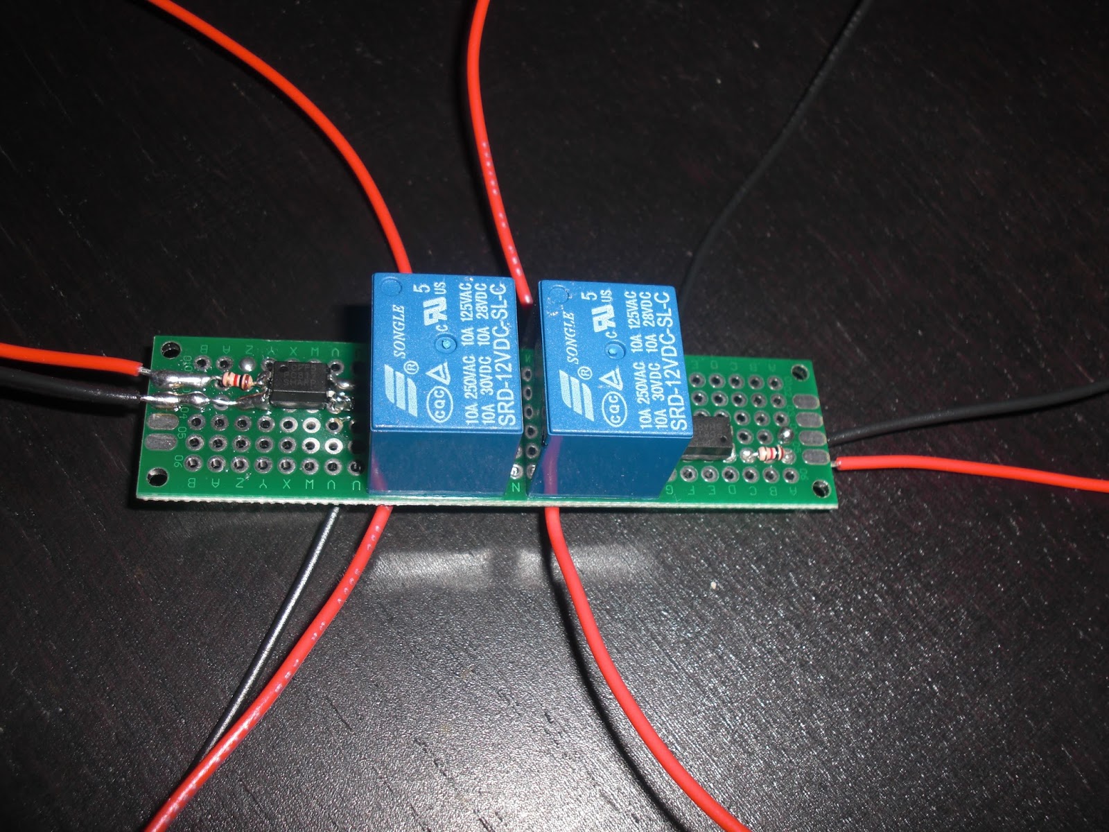
The momentary buttons to activate the various sound FX on the Adafruit board I will hook up to both my Lower Console's Space Matt buttons and my Switch Pod buttons. So far on the sound FX board I have:
- Knight Rider Theme (Narrated)
- Knight Rider Theme (Un-Narrated)
- File Open Sound FX
- File Close Sound FX
- Scanner Sound (Loop)
- Radar Sound (Loop)
- Turboboost
- K.I.T.T. Introduction
- Surveillance Mode FX
The Knight Rider themes I have set on the board to play in next order so when you press the button the first theme plays and at the end of the theme when you press the button again the other version of the them plays.
The File Open sound FX I have sent to just play when the button is pressed, my thought is that I will have those sounds play when I turn on the LCD Screen or GPS Screen.
File Close sound FX will play when I turn off either monitor.
Scanner sound FX loop I have set as a "Latching" function on the Adafruit board, the sound plays until the button is pressed again, so looping sounds are best for the boards "Latching" function.
Same set up for the Radar and Surveillance sound FX loops.
Turboboost FX is set as just a single play on button press same as K.I.T.T.s introduction. I could very easily add other introductions and have those play in a random order as the Adafruit sound FX board has a very nice feature for playing random sound files too, but for now I'm just using the classic K.I.T.T. introduction ;)
Here is a little additional work done on the diagram to include a power on off switch and to use the option of either a Relay or Optocoupler as switch option for the momentary button to activate the board sounds.
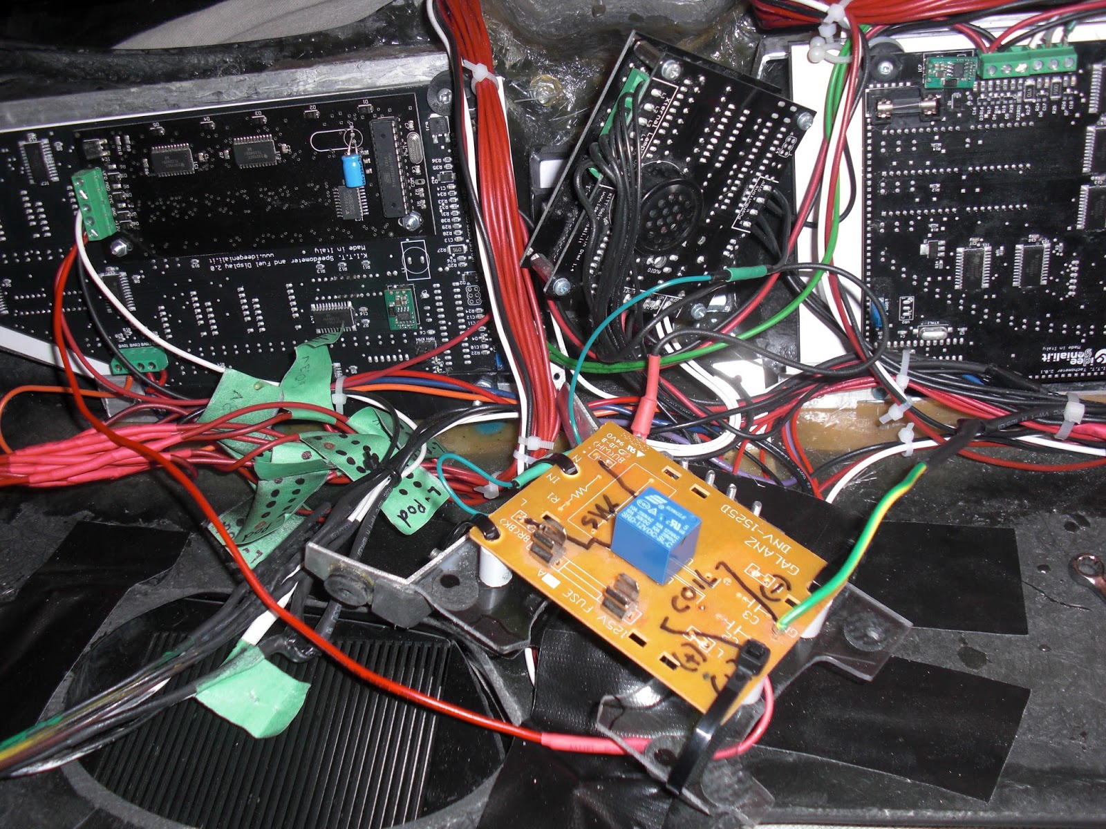
Wednesday, July 22, 2015
Adafruit Mini 2MB Sound FX Board Test
So I finally got around to testing out the Adafruit 2MB Flash Sound FX board I had picked up quite some time ago, I had been meaning to get around to it but was constantly getting side tracked with so many other projects. Today I hooked up the USB cord and plugged in the mini board and copied over the WAV and OGG files with the correct naming convention as per the instructions on the Adafruit web site. The board works like a charm and is very simple to use just like they say. This will be perfect for some sound FX that I know will get used a lot and I think should be built right into my K.I.T.T. project. I have a demo video here, I do apologize for the focus though but it's gets the point across as to what is going on and how easy it will be to hook up these contacts that activate the sounds on the board very easily to some of my Switch Pod and Space Matt buttons.
Monday, July 20, 2015
OEM Dash Center Air Vent Modifications
I had been sort of wondering for some time what to do about redirecting the airflow from the vent located in the middle of the stock OEM dash. I figured since I had that cover plate I had made out of Lexan plastic to help separate and protect the backs of the Knight Rider dash circuit boards from coming into contact with a bunch of loose flying wires I would see about somehow giving it another job as well, like attaching some sort of vent to allow the air to from through that vent opening in the OEM dash and more out from under the dash.
So what I came up with was to first make a rectangular box made from some high density foam rubber I picked up from a Craft store (Micheal's). I used black Gorilla Tape to hold the shape of the foam box together and then inserted it into the OEM dash vent opening. (above left). It's a snug fit and friction alone seems to keep it securely in place although I could glue it in with some contact cement if I find I need too. This box brings the vent opening up close to the back over my Lexan plastic cover plate.
I'm not yet ready to secure the cover plate into place yet as I am still doing a fair bit of electrical wiring work in that area of the dash but when I am finished the cover plate will be secured into place and should serve the double purpose of protecting my wires from coming into contact with the back of my Knight Rider dash circuit boards and provide a nice opening to allow the airflow from the middle vent to flow downwards out under the dash.
Thursday, July 16, 2015
Parking and Headlights Lower Console Auxiliary Switch Wiring
I think I have everything I need to give this a shot, I need to pick up some more solder and I'm not sure if I want to mount my Diodes onto a small piece of PCB board or just do them as "in-line" Diodes. But it looks like I should be pretty close to doing a video to show how this works. From what I can see of the wiring diagram it looks like it would be easy to even use one of the Upper Console DPDT lighted rockers for the Parking and Headlights too. ;)
NOTE:
OK after some Multimeter testing on the stock OEM switch I had kicking around from the parts car it would appear that in the "OFF" position that there is a continuity between the White and Orange wire. Based on those findings I am going to try this diagram suggested by Mark Rolfe out as it seems to make the most sense with the white wire included into the scenario.
Sunday, July 12, 2015
Headlights Switch Relocation
I then cut out a hole in the plastic dash trim (left) big enough for the Headlights Switch and then fit the switch into place (right). I put the plug back on the end and test fit the whole thing back into the dash. I had to use my Dremel to do a little cutting in the stock OEM dash to make the plug fit into the space better because it's a big fat beast of a plug but with a little cutting work it can be made to fit nicely to the hole. I fed the wires from the plug in through the hole and down in through the underside of the dash, that way I can solder them the the other wires I have going into the wires that came out of the area of the stock OEM dash that the original plug was attached too. Basically all I am doing is extending the wires and relocating the switch to somewhere more convenient.
Here is the final assembly in place, it's not screwed in yet as I have a lot more mucking about to do with wiring and such but it's in place and has been tested out, check out the two videos in my previous postings to see how that turned out. ;)
Tuesday, July 7, 2015
DTMF Tone Request Experimentations
In making sure that I well isolate the Voice Box's DTMF tone request from any momentary buttons I have I figured I would rig up a mini Songo 12V Relay very close to the Voce Box. Now what happens here is that when a DTMF Tone request is called by any momentary button I have hooked up to a wire that I am calling "DTMF Tone Request" THAT wire goes to the magnetic coil of this mini Songo 12V Relay's Ground (-), the other side of the magnetic coil goes to 12V (+). So this then trips the Relay's internal isolated switch which I then have connected to both the Voice Box's Ground (-) and also the DTMF Tone Request port. You will have to excuse my somewhat over sized piece of PCB board it was all I had kicking around that I could use to mount this small relay onto and connect wires too. I'll most likely change it later when I get some smaller pieces of PCB Proto-Board. The wires from the Switch Pods that request the DTMF tone I just have going directly into the Voice Box's DTMF Tone request port.
Now the other part of today's fun was to wire up my Relays board for some experimentation just to make sure that I am understanding correctly just what is going on with this thing and how it interacts with my buttons. All of this stuff gets pretty complicated if you are new to electronics like me. ;) My latest video that I posted to my blog explains best and visually how I have it all hooked up. But basically the Ground pulse buttons from my Space Matt buttons go into the ports on the board that connect to the Diodes, they connect to the DTMF Tone Request wire and also to the individual relays on the board. Each relays gets it's own ground pulse from each of the Space Matt buttons activating the Relays internal switch which I can hook up to any device I want to activate, in my case 5 of the Space Matt buttons are simply activating buttons that control the setting for my LCD screen. Although I have not yet hooked it up, a 6th button will cycle the Message Centre while producing a DTMF tone with each press of the button. The rest of the Space Matt buttons I don't have plans for just yet.
My Voice Projection unit activation button is wired up the same way as the Dash Power Button and makes a connection to ground to activate the Step Relay, this one was a little more tricky. You can see in the image above (middle left) that branching off from the wire that comes from the Normally Open terminal of the V.P. power button that I have placed a Diode in-line connecting to the DTMF Tone Request block.... which I moved onto the back of my Relays Board. Without the Diode in place the Space Matt buttons would activate the Step Relay for the Voice Projection unit as well, not good, so the Diode sure takes care of that as it only allows current to travel in one direction... taking me a while to get the hang of that but it works and it's cool... gotta love electronics ;)
So now with all of this in place I'll have to test it out on the Voice Box once the replacement I.C. Chip 01 comes in the mail. If everything works out well, and so far I can't see what not as a Relay does what a Relay does ;) But as I say if all goes well I can look into experimenting with the Optocouplers when they arrive and see if I can make a set up like this that takes up a lot less space. This would be fine if I only wanted to use a small amount of my Space Matt buttons but I can see eventually wanting to use more down the road as I trick out K.I.T.T. with more cool gadgets ;)
Subscribe to:
Posts (Atom)