I have put together the Adafruit Mini Flash SFX Sound Board along with the TDA2030A Amplifier module onto a piece of Protoboard. Took me a little while to solder out the pins and Speaker connection screw terminal block so I could solder the pins onto the back of the board and add some more pins for where the speaker connections go. I relocated the original screw terminal block from the Amplifier board to just the right of the module on the Protoboard and then connected the two with some jumper wires.
Right now I am powering the Adafruit SFX board with a USB cable but I have some LM7805 power regulators on order so I can just wire in 12V and split a portion of that off to power the Adafruit board with the 5V output from the LN7805.

 I also started to make my Optocoupler board for the Sound Effects that will be generated from the Space Matt buttons. Some of the sound effects will be generated from the Switch Pods and I will not need the DTMF request wire that I have worked into this board as the Switch Pods already send a DTMF tone request. But I figure just incase I ever re-purpose these little boards for something different in the future it might be a good idea to have the ability already on the little boards. Here is a diagram of how I have the Optocoupler board wired (above left). Some other buttons I may need to get a little tricky with using that 555 timer board to request the Monitor Activation Sound when I turn on the lower console buttons for either the GPS or LCD screen as they are latching buttons and the Adafruit SFX board just needs momentary connections to activate any of the sounds on the pins.


 I currently have plugged into the Breadboard a bunch of wires that are going into the Arduino ports that are coded for stuff but not actually hooked up to a Relay Module yet. I need to get a 2nd 16 Channel Relay Module and modify that one just like the one here, but for now that is kind of optional for me as most of the main functions are routed through the first Relay Module. The 2nd Relay Module would be more for all the cool extras. Although you can mix and match and assign ANY of the outputs to whatever Relay you want so for example if you don't use the Auto Doors but are going to use the S.I.D. function all you would need to do is connect up the stuff you are using, The interface would still go through the motions just without the Relay hooked up it would not actually perform the "Physical" function.... but I think you get that.
 The other thing I can do now is hook up the LDR and Temperature Sensors, I think I am going to install those two up into the Upper Console as that seems a logical place. The LDR Sensor I can mount so that it is facing forwards out the front part of the Upper Console that way it will get it's light values from whatever comes through the front Windshield. The Temperature Sensor seems to make sense to me to be up in the Upper Console as that way it is away from the Heater and Air Vents which I think would cause inaccurate readings to occur, that's my thought on it anyways, but I can see that being on of the best places. The Sensor for the Compass however is a whole other animal right now so not sure about that one. Getting Closer though :D

 I also started to make my Optocoupler board for the Sound Effects that will be generated from the Space Matt buttons. Some of the sound effects will be generated from the Switch Pods and I will not need the DTMF request wire that I have worked into this board as the Switch Pods already send a DTMF tone request. But I figure just incase I ever re-purpose these little boards for something different in the future it might be a good idea to have the ability already on the little boards. Here is a diagram of how I have the Optocoupler board wired (above left). Some other buttons I may need to get a little tricky with using that 555 timer board to request the Monitor Activation Sound when I turn on the lower console buttons for either the GPS or LCD screen as they are latching buttons and the Adafruit SFX board just needs momentary connections to activate any of the sounds on the pins.
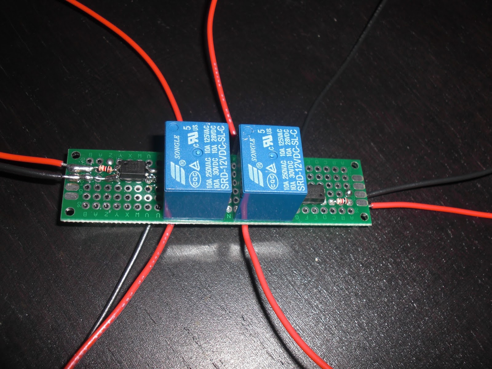
 I did up a quick diagram of the little PCB board I made with some great help from Andrea lannaccone from Face Book. There are smaller ways to do this but this is pretty small too, you can do this type of switching with a Transistor too. For what I am doing with my Top Countdown Indicator lights to activate the switch lights on my Lower Console I only need one side of the board but there was room on the board to have the same ability twice so at least I have an extra setup for should I need to do something similar again. :)