Showing posts with label step relays. Show all posts

Sunday, October 25, 2015

A Better Relays Board Installed

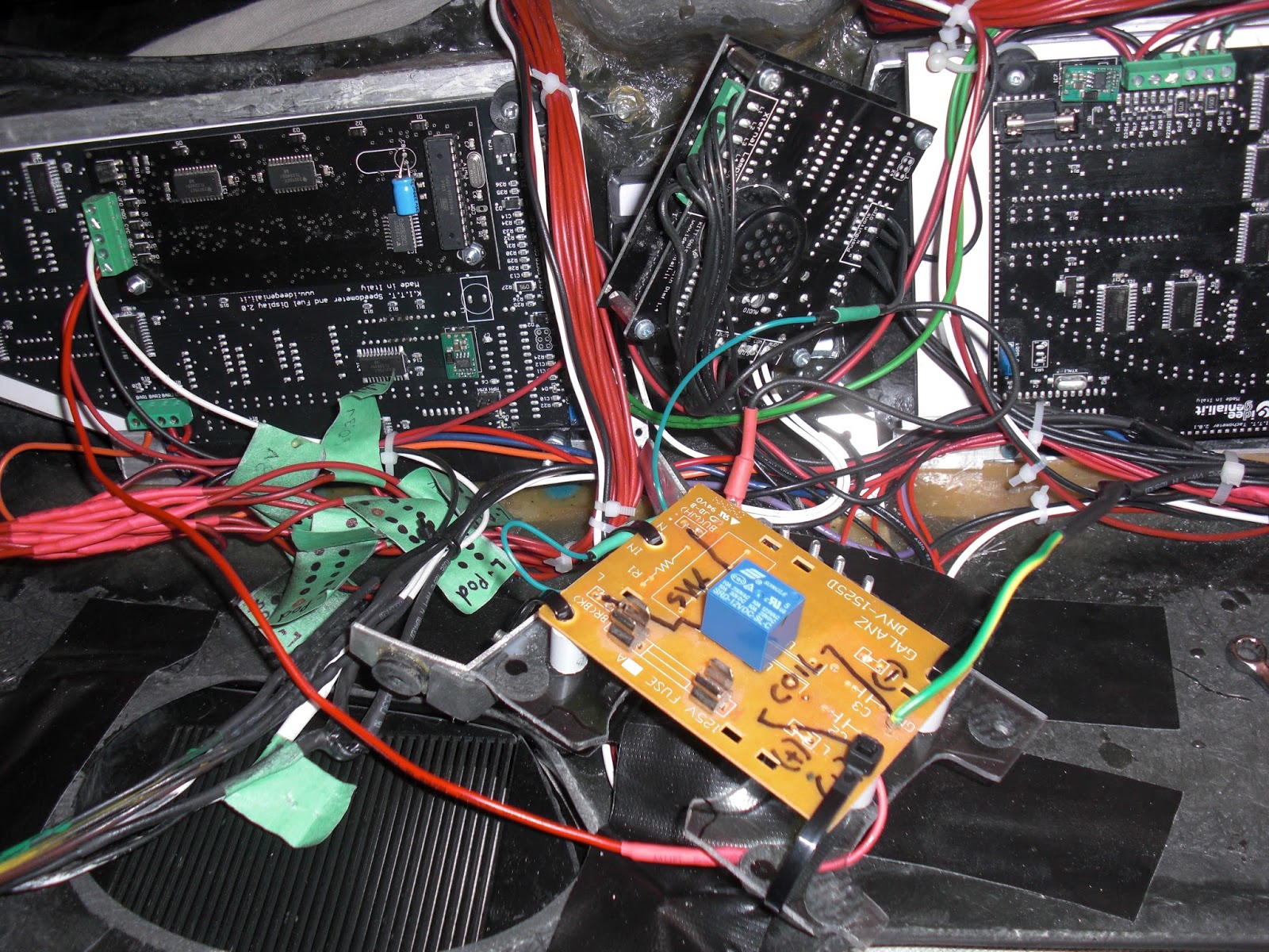
It took me a little while to install he new relays board I made with Rectifier Bridge Diodes before each of the relays in order to cure that problem I was having with the SFX module I had put together. I had to do a fair amount of shuffling things around on my stock dash to make things fit right. (left).

You may recall from earlier posts when I was working on my Voice Projection Unit that I had the on/off button hooked up to a Step Relay that was located about where my new relays board is now. What I ended up doing was moving the Step Relay to the same location as the on/off button for the V.P. Unit and mounting it behind the panel that the button is mounted too (right). I also made up a small Rectifier Diode Bridge module with terminal blocks that I could easily wire up to between the on/off button to the Step Relay and mounting that in behind the panel as well. I like it a lot better now because when you press the V.P. button the loud click from the Step Relay is right behind where the switch is located and not on the other side of the dash like before, so in many way it makes more sense this way.

Tuesday, July 7, 2015

DTMF Tone Request Experimentations


In making sure that I well isolate the Voice Box's DTMF tone request from any momentary buttons I have I figured I would rig up a mini Songo 12V Relay very close to the Voce Box. Now what happens here is that when a DTMF Tone request is called by any momentary button I have hooked up to a wire that I am calling "DTMF Tone Request" THAT wire goes to the magnetic coil of this mini Songo 12V Relay's Ground (-), the other side of the magnetic coil goes to 12V (+). So this then trips the Relay's internal isolated switch which I then have connected to both the Voice Box's Ground (-) and also the DTMF Tone Request port. You will have to excuse my somewhat over sized piece of PCB board it was all I had kicking around that I could use to mount this small relay onto and connect wires too. I'll most likely change it later when I get some smaller pieces of PCB Proto-Board. The wires from the Switch Pods that request the DTMF tone I just have going directly into the Voice Box's DTMF Tone request port.


Now the other part of today's fun was to wire up my Relays board for some experimentation just to make sure that I am understanding correctly just what is going on with this thing and how it interacts with my buttons. All of this stuff gets pretty complicated if you are new to electronics like me. ;) My latest video that I posted to my blog explains best and visually how I have it all hooked up. But basically the Ground pulse buttons from my Space Matt buttons go into the ports on the board that connect to the Diodes, they connect to the DTMF Tone Request wire and also to the individual relays on the board. Each relays gets it's own ground pulse from each of the Space Matt buttons activating the Relays internal switch which I can hook up to any device I want to activate, in my case 5 of the Space Matt buttons are simply activating buttons that control the setting for my LCD screen. Although I have not yet hooked it up, a 6th button will cycle the Message Centre while producing a DTMF tone with each press of the button. The rest of the Space Matt buttons I don't have plans for just yet.

My Voice Projection unit activation button is wired up the same way as the Dash Power Button and makes a connection to ground to activate the Step Relay, this one was a little more tricky. You can see in the image above (middle left) that branching off from the wire that comes from the Normally Open terminal of the V.P. power button that I have placed a Diode in-line connecting to the DTMF Tone Request block.... which I moved onto the back of my Relays Board. Without the Diode in place the Space Matt buttons would activate the Step Relay for the Voice Projection unit as well, not good, so the Diode sure takes care of that as it only allows current to travel in one direction... taking me a while to get the hang of that but it works and it's cool... gotta love electronics ;)

So now with all of this in place I'll have to test it out on the Voice Box once the replacement I.C. Chip 01 comes in the mail. If everything works out well, and so far I can't see what not as a Relay does what a Relay does ;) But as I say if all goes well I can look into experimenting with the Optocouplers when they arrive and see if I can make a set up like this that takes up a lot less space. This would be fine if I only wanted to use a small amount of my Space Matt buttons but I can see eventually wanting to use more down the road as I trick out K.I.T.T. with more cool gadgets ;)   


Saturday, September 20, 2014

General Update - Getting Close To Having The Dash Wired

It's taken a lot of annoying questions and pestering to finally get what I think is the correct wiring order of the dash electronics. I'm a little surprised that the suppliers of these electronics don't put something a little more inclusive as far as wiring instructions given that I can't possibly be the only one out there attempting a project like this that knows very little about  electronics. It would make the job go a hell of a lot smoother and take less time instead of all the running around in different forums posting question after question trying to get confirmation on if something is correct, if I understand it right... I am trying to learn, and it's by the asking of questions we learn is it not?

Anyways I was to learn that I needed a Step relay for the Power switch among the P.A.N.P. group of push button switches. It then too a very long time (All day) to find a place on-line willing to ship to Canada... that was a joy treat of frustration I'm here to tell you. So I finally get the one recommended to me only to discover it has six terminals verses the one in the diagram that has only four. To make things even more confusing the diagram originally did not have the terminals numbered, I had to pester, and pester until I got that information. So that was part of the problem finally licked as to just what the hell those terminals were on the Step Relay.

Next issue was how does this relay relate to the one I was recommended. So again it was back to the pestering to try and get an answer to that nagging question. I was then told NOT to use terminals 3 and 4 on the Step Relay, which was fine considering my Relay seemed to be missing those screws for some reason, perhaps that very reason? I just don't know.


So now we know what NOT to use on the Relay but still no definitive or certain information on the wiring order to the Relay. We all know these are important things to know because these are very expensive electronics and we don't need to be replacing them due to faulty wiring now do we??

Some more pestering later (all of this pestering takes days btw), I got information that 3 and 4 on that Relay don't do anything, which may explain the missing screws, and that A1 on the Relay is 3 on my schematic, and that 1 and 2 are the switch. I hope to Hades that is correct?

We are getting closer, and closer to where I should be able to fire up the dash electronics for a test.... and I hope NOT the word "Fire Up." I will do a lot more pestering yet before I feel confident enough to hook the dash up to power and give everything a test before fitting the dash into the car.

Another thing that had been bugging me was trying to figure out how people test out their dash electronics out side of their cars once they have put everything together. I was told that something like a Battery Booster Pack like the one I have here is good for testing out the electronics. So I picked up a Motomaster Eliminator Booster pack. My next dilemma albeit a small one was the type of connector the Booster Pack has. All I need is a Positive and a Ground wire to hook ultimately up to the dash electronics. But not being very familiar with those "Cigar" type plugs I was not sure which of the connections points was which. So into Photoshop to do what I'm best at and that's creating graphics to make an illustration of the type of connector to better get my question across. Now my suspicion was that the middle connection point was the (+) Positive because it had the fuse inside of it. The side spring clips had to be the (-) Ground I figured.... But again best to be doubly sure about this stuff.


As it turns out this is the way these plugs are generally configured. I was told that sometimes only one of the side spring clips is actually grounded, wouldn't that just figure?? So I took apart both ends of the plug to have a look. Fortunately both sides of the plug side springs are grounded. No I could I would imagine just place small Alligator Clips onto one of the Side Springs (-) and one onto the Tip of the plug (+) but that seems a bit of a giggly connection should the wire accidentally fall or get bumped and then the clips could just simply pop off, most likely the tip seeing how it's smooth and not much for the Alligator clip to hold onto. I went out and bought another type of "Cigar" plug that has a thinner wire on. 


So now I'm wondering if that thin wire would be strong enough to handle the current for all of the dash electronics. I was told that the Ignition wire is sufficient for powering your dash electronic too.

A lot of these issues mentioned above are things I am trying g to get confirmation on, good solid answers, Yay or Nay, otherwise I'm very apprehensive about hooking my dash wires up to power, it has to be done at some point but I'm trying to get as much information and confirmation of that information as possible before I do so. One other thing I am not sure of is that if you look at my first diagram at the top of this posting you can see how I have the dash electronics wired to each other in a "Daisy Chain" sort of fashion, I have been told this is OK, I just used the wires that were attached onto the dash electronics when they arrived from Italy. I'm wondering if I should change them to a slightly thicker 18 AWG wire or if they are more than fine with the wires they came with...??

Anyways.... So many variable to try and sort through.... it's a no wonder I have not gotten this dash installed over the summer months. Research, research, research takes a lot of time.